
Gear geometry#
The geometry is not just a picture of the tooth: it determines where the load acts, how many teeth share it and how much material remains at the root. Start with the involute, then follow the rack that generates the tooth and finally bring two gears into mesh.
Why an involute?#
Imagine unwinding a taut string from a circle. The end of the string traces an involute; the circle is its base circle. The common normal of two involute flanks stays tangent to their base circles, which gives a constant velocity ratio even when the centre distance changes slightly.
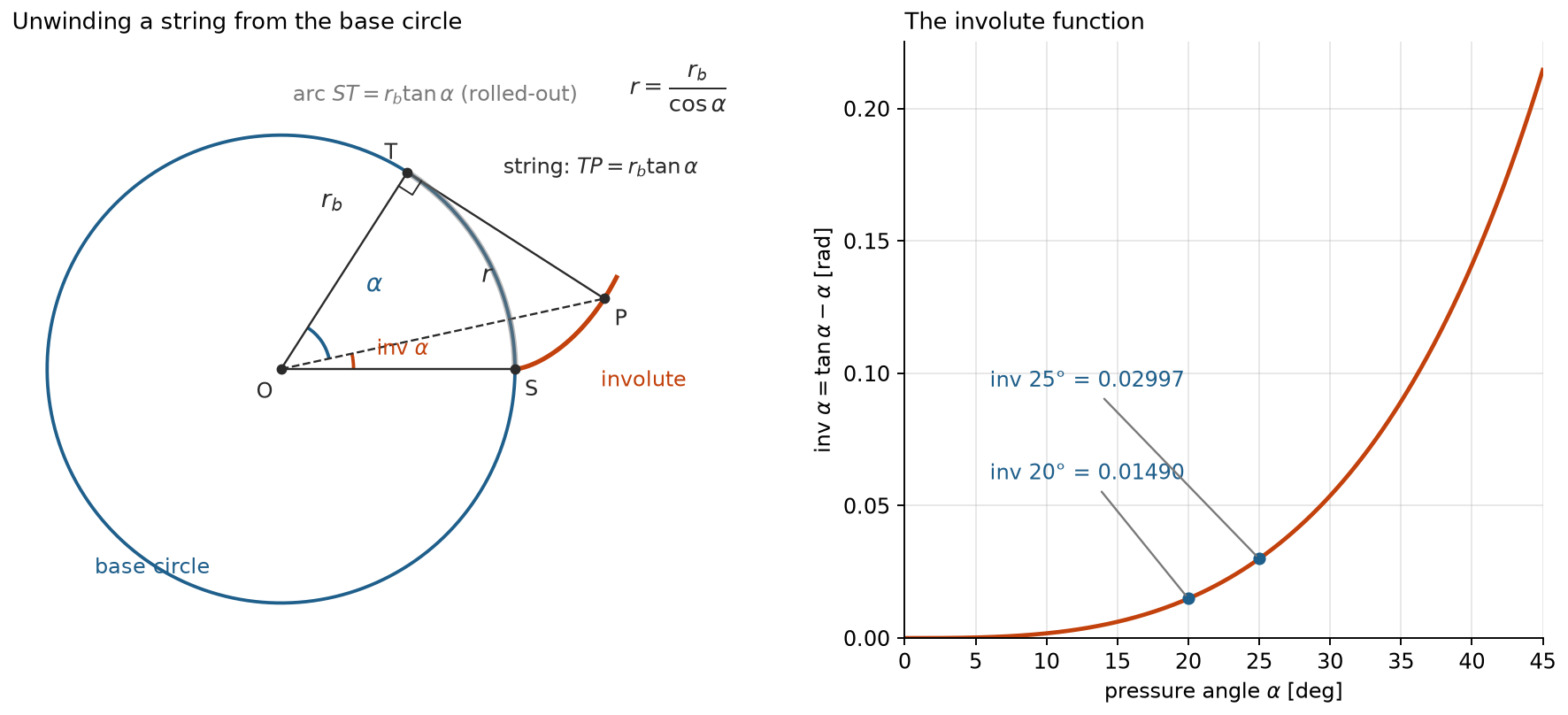
The base circle and the unwound tangent define the flank.#
The involute function is
The angle inside this expression is in radians. The public helpers
gearbox.mathutils.involute() and gearbox.mathutils.inverse_involute()
accept and return degrees, respectively; the function value itself is dimensionless.
At radius \(r\), \(\cos\alpha_r=r_b/r\). Below the base circle there is no involute flank: the
root is a different, generated curve.
The rack and the reference dimensions#
gearbox.models.Tool describes the basic rack. Its addendum, dedendum and corner radius
are coefficients multiplied by the normal module \(m_n\). The familiar rack uses 1.0, 1.25 and 0.38,
with clearance 0.25 and normal pressure angle \(20^\circ\). See
ISO 53 for basic rack definitions and
ISO 21771 for involute geometry terminology.
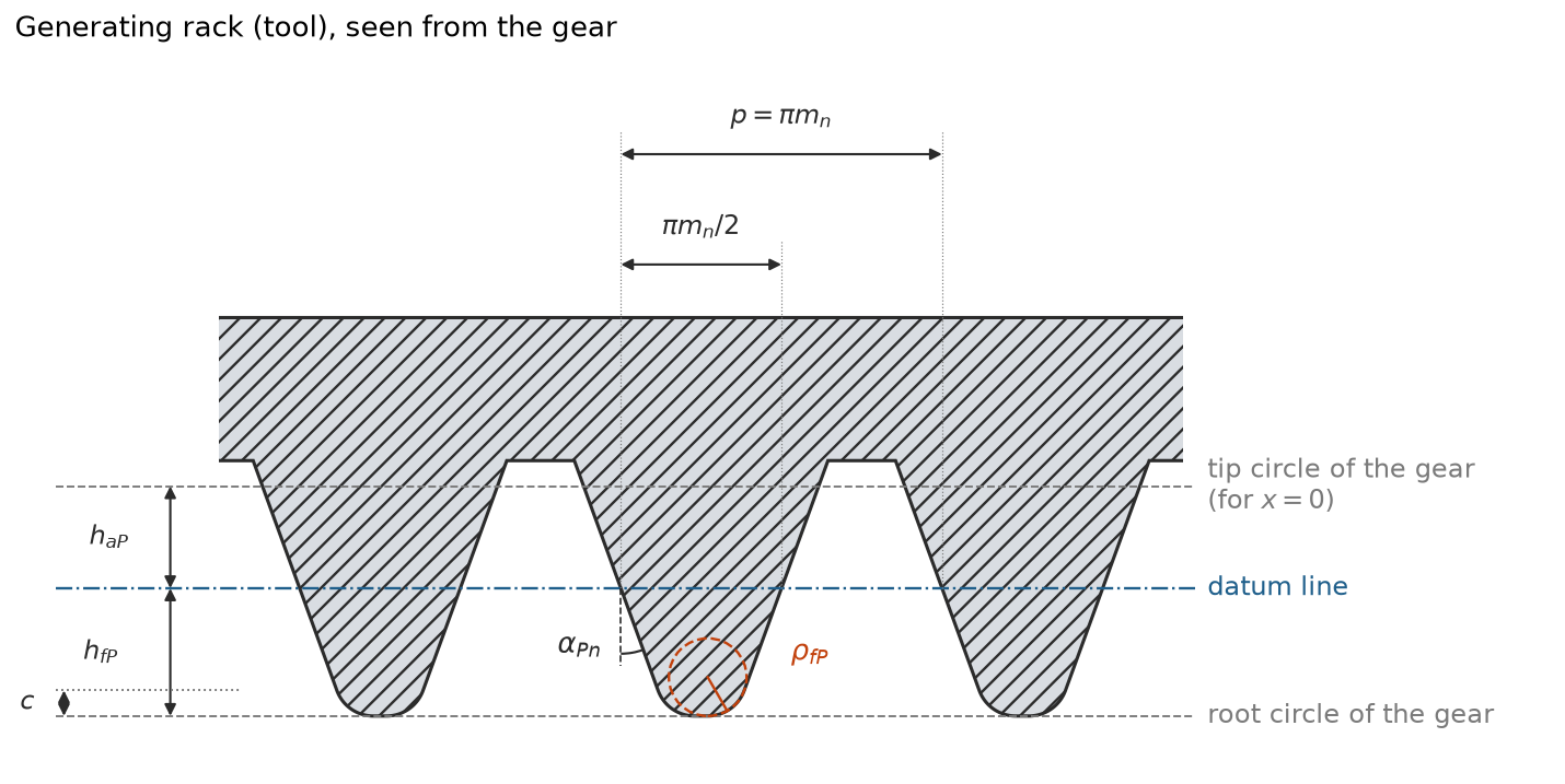
The rounded rack tip generates the gear root; it is not the radius of the finished root fillet.#
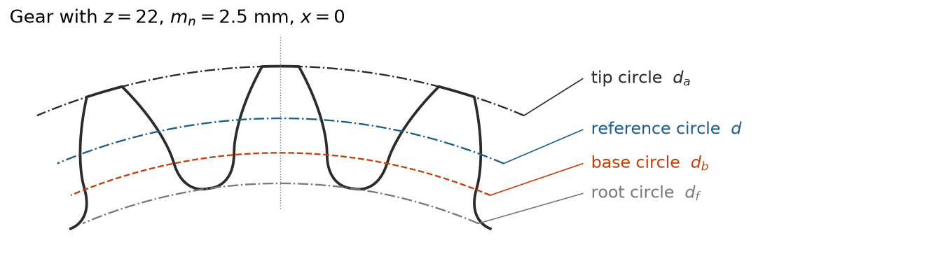
For an external helical gear, the implemented reference relations are
These correspond to transverse_module, transverse_pressure_angle, reference_diameter,
base_diameter, tip_diameter and root_diameter on gearbox.models.Gear.
dedendum separately uses the tool’s dedendum_coefficient; choose mutually consistent rack
coefficients rather than assuming arbitrary addendum, dedendum and clearance inputs are reconciled.
Profile shift and undercut#
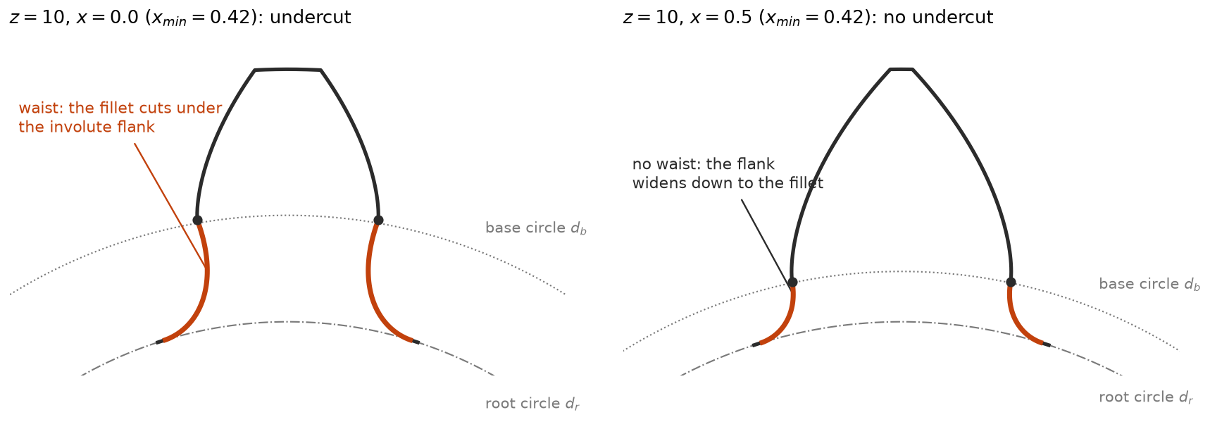
A positive shift moves the rack outward by \(xm_n\). The tooth becomes thicker at the reference circle and usually stronger at the root, but its tip becomes thinner. The normal reference thickness is \(s_n=m_n(\pi/2+2x\tan\alpha_n)\).
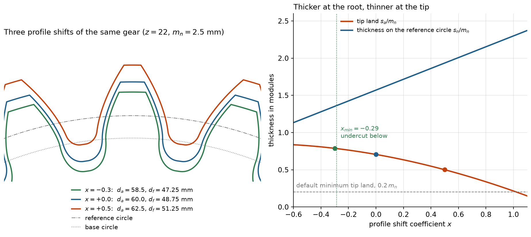
The package’s theoretical undercut limit for an external gear is
Below that limit the cutter removes part of the involute near the root. Avoiding undercut is not the only constraint: the tip must remain thick enough and the pair must maintain adequate contact ratio. The Optimization of profile shifts chapter combines these constraints rather than optimizing one stress without checking the rest.
The generated root fillet#
gearbox.profile.ToothProfile rolls the rack without slip on the reference circle.
The envelope of the rounded rack tip forms a trochoid-like root fillet, joined to the involute
at the root form diameter \(d_{Ff}\). This diameter is not generally the base diameter.
For helical gears the normal circular rack rounding becomes an ellipse in the transverse section.
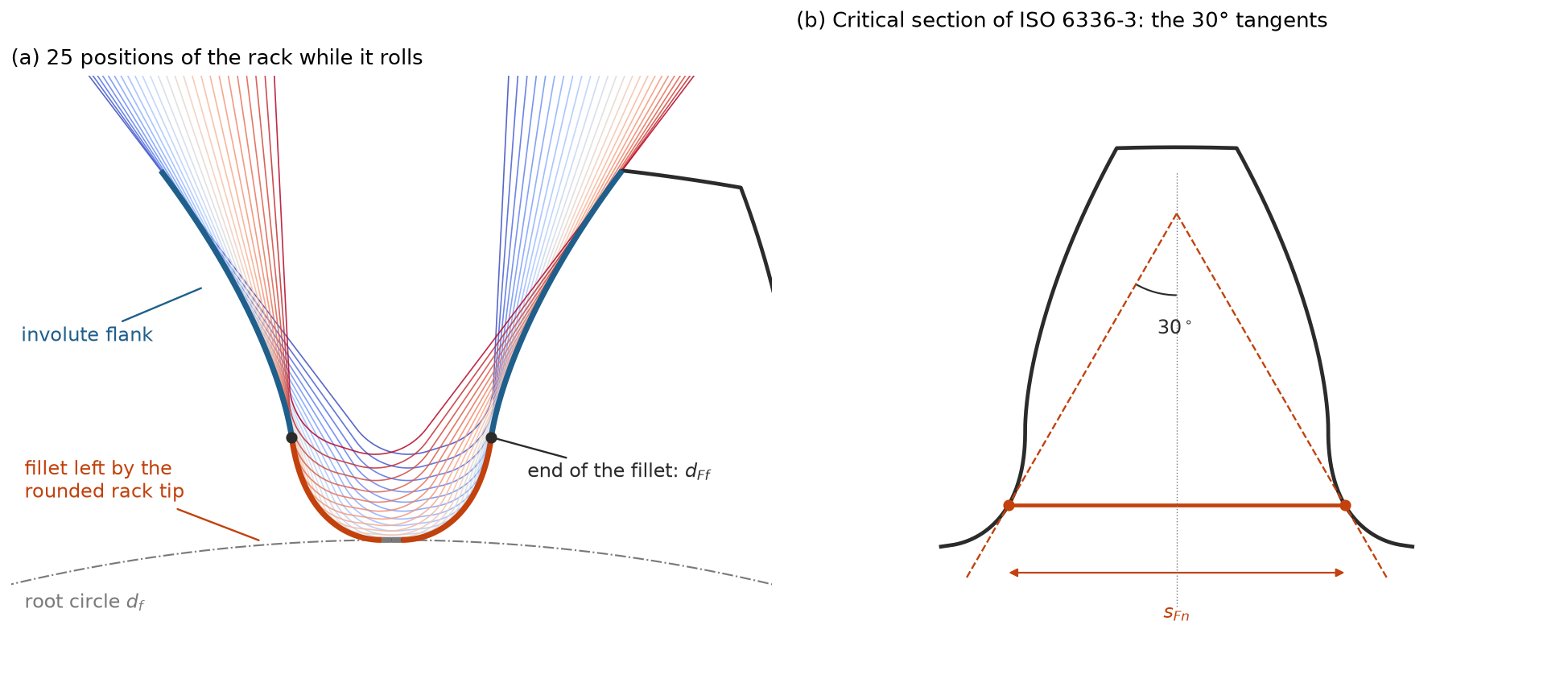
The half-tooth coordinates run from the centre of a gap to the tooth tip. The FEM mesher mirrors and repeats this profile. The geometry generator supports external rack-generated gears; the analytical ISO root-strength calculation also has a separate shaper-cutter model. Do not confuse those two capabilities.
Bringing two gears into mesh#
gearbox.transmission.Transmission calculates the transverse working pressure angle from
Keeping the sum of shifts fixed therefore preserves the working centre distance. The transverse contact ratio is the active path length divided by transverse base pitch,
See ISO 6336-2, clause 8.3. The implementation limits the path by the base circles, but does not yet apply the active root diameter limits. That omission matters for unusual profiles and interference-sensitive designs.
For ordinary spur pairs with \(1<\varepsilon_\alpha<2\), A is the start of contact, C the pitch
point and E the end. B and D delimit the single-pair zone; two pairs share load outside it.
gearbox.fem.post.LineOfAction exposes these positions and the associated geometry.
Internal and double helical gears#
Set
internal=Trueon the wheel, not the pinion. Give the tooth count as a positive input;signed_number_of_teeth, wheel diameters, ratio and centre distances are negative under the ISO convention. Physical sizes remain their magnitudes. The library does not perform a complete manufacturing-interference check for an internal pair.For double helicals,
face_widthis the width \(b_B\) of one helix, excluding the gap.total_face_widthis \(2b_B\); overlap uses \(b_B\). This analytical capability is not a promise that the FEM generator builds the full two-handed geometry.
Flank tolerances#
gearbox.models.Gear.tolerances implements the flank tolerance relations of
ISO 1328-1:2013, formulae (5)–(12). Class \(A\) scales the unrounded
class-5 values by \(\sqrt2^{A-5}\). Total profile and helix deviations combine their components
quadratically before rounding. Values are returned in micrometres.
The implemented size checks cover \(5\le z\le1000\), \(5\le |d|\le15000\) mm, \(0.5\le m_n\le70\) mm, \(4\le b\le1200\) mm and \(0\le\beta\le45^\circ\). Runout and tooth-thickness tolerances are not implemented. Accuracy classes also feed the dynamic and load-distribution factors: a geometric tolerance is not merely a drawing annotation.