
Optimization of profile shifts#
Once the pair is described, the cheapest lever you have on its strength is the profile shift.
Moving the rack away from the pinion thickens its tooth root and weakens the tip; moving it towards
the wheel does the opposite. If the sum \(x_1 + x_2\) stays fixed, the centre distance does not change
(see Gear geometry), so you can trade strength between the two gears at no cost in
housing. gearbox.optimization explores that trade for you.
Note
The helpers never change the sum \(x_1 + x_2\) and never modify your objects: they return the
coefficients, and you build the new pair with dataclasses.replace.
The design space#
For a fixed sum, the only free variable is the pinion shift \(x_1\), with \(x_2 = \sum x - x_1\). A value of \(x_1\) is feasible when
neither gear is undercut: \(x_i \ge x_{\min,i} = h_{aP}^* - \tfrac{1}{2} z_{n,i} \sin^2\alpha_n\) (
minimum_profile_shift_coefficient),the transverse tooth thickness at the tip circle of both gears is at least
minimum_tip_landmodules (0.2 by default, so the tip is not pointed), andthe transverse contact ratio is at least
minimum_contact_ratio(1.2 by default).
feasible_pinion_profile_shift_range() samples the constraints on a
grid, refines the edges of the widest feasible interval with Brent’s method and returns
\((x_{1,\min},\, x_{1,\max})\). It raises ValueError if nothing is feasible, which usually means
the sum is too small to avoid undercut in both gears.
from dataclasses import replace
from gearbox import optimization as opt

low, high = opt.feasible_pinion_profile_shift_range(transmission)   # pair of "A first calculation"
print(f"x1 between {low:.3f} and {high:.3f}")                       # -0.287 and 1.023
The lower limit is the undercut limit of the pinion (\(x_{\min,1} = -0.287\)); the upper one is set by the tip land of the pinion, which gets pointed as it is shifted outwards.
The algorithm, step by step#
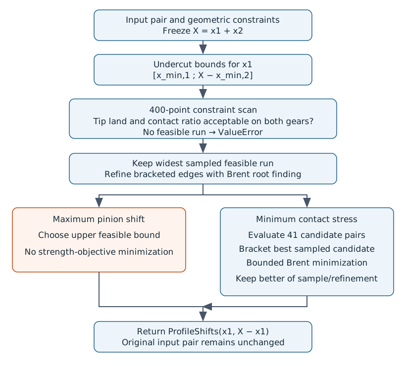
Both objectives preserve the sum of shifts and share the same feasibility stage.#
This pseudocode follows the implementation, including its finite sampling. Brent root finding locates constraint boundaries; bounded Brent minimization refines a stress objective. These are different numerical problems.
FEASIBLE_RANGE(pair, tip_min = 0.2, ratio_min = 1.2):
    reject an internal wheel
    X ← pair.x1 + pair.x2
    lower ← pinion undercut limit
    upper ← X − wheel undercut limit
    if lower > upper: raise ValueError

    MARGIN(x1):
        candidate ← immutable copy with shifts (x1, X − x1)
        return minimum of:
            pinion tip thickness / module − tip_min
            wheel tip thickness / module − tip_min
            transverse contact ratio − ratio_min

    grid ← 400 equally spaced values in [lower, upper]
    feasible ← MARGIN(x1) ≥ 0 at each sample
    runs ← contiguous runs of feasible samples
    if no run exists: raise ValueError
    keep the widest sampled run
    refine its edges with Brent root finding where sign-change brackets exist
    return refined lower and upper bounds

MAXIMUM_PROFILE_SHIFTS(pair):
    lower, upper ← FEASIBLE_RANGE(pair)
    return (upper, pair.shift_sum − upper)

MINIMUM_CONTACT_STRESS_PROFILE_SHIFTS(pair, standard):
    lower, upper ← FEASIBLE_RANGE(pair)
    X ← pair.shift_sum

    OBJECTIVE(x1):
        candidate ← immutable copy with shifts (x1, X − x1)
        ISO: return maximum of pinion and wheel contact stresses
        AGMA: return the calculated common contact stress

    sample OBJECTIVE at 41 equally spaced values in [lower, upper]
    best ← sample with lowest stress
    bracket ← immediate neighbours of best, clipped to interval bounds
    refined ← bounded Brent minimization in that bracket
    keep refined only if its stress is no higher than the best sample
    return (chosen x1, X − chosen x1)
Guarantees and numerical limits#
The objective need not be unimodal over the whole interval: the initial sampling finds a promising neighbourhood before local refinement. This is not a proof of the global minimum. A 400-point constraint scan can miss a narrow feasible island; the algorithm retains only the widest sampled interval. A 41-point objective scan can miss a narrow minimum. Sensitive designs warrant an independent denser search.
The defaults are software design constraints, not universal limits imposed by every standard. The helpers do not add manufacturing-interference checks, scuffing criteria or a multi-objective optimizer balancing all safety factors.
Two objectives#
Strongest pinion root — maximum_profile_shifts() returns the
largest feasible \(x_1\). A thicker pinion root lowers its bending stress, but it moves the load to
the wheel: the wheel gets a negative shift, a thinner root and a shorter contact path.
Lowest contact stress — minimum_contact_stress_profile_shifts()
samples the stress over the feasible range with the standard of your choice ("ISO" or "AGMA";
for ISO the larger of the two gears governs) and refines the best sample with a bounded Brent
minimization. It does not assume the curve is monotonic or unimodal, which matters because
\(\varepsilon_\alpha\), \(Z_B\) and \(Z_D\) change in steps.
from gearbox.standards import iso6336

pair = replace(transmission,                     # start from x1 = 0.3, x2 = -0.3
    pinion=replace(transmission.pinion, profile_shift_coefficient=0.3),
    wheel=replace(transmission.wheel, profile_shift_coefficient=-0.3))

def with_shifts(pair, shifts):
    return replace(pair,
        pinion=replace(pair.pinion, profile_shift_coefficient=shifts.pinion),
        wheel=replace(pair.wheel, profile_shift_coefficient=shifts.wheel))

for name, shifts in {"maximum": opt.maximum_profile_shifts(pair),
                     "minimum contact stress": opt.minimum_contact_stress_profile_shifts(pair)}.items():
    candidate = with_shifts(pair, shifts)
    pitting = iso6336.calculate_pitting(candidate)
    bending = iso6336.calculate_bending(candidate)
    print(f"{name:24s} x1={shifts.pinion:+.3f}  sigma_H={pitting.contact_stress_pinion:.0f}  "
          f"sigma_F1={bending.tooth_root_stress_pinion:.0f}  sigma_F2={bending.tooth_root_stress_wheel:.0f}")
For this pair (22/40 teeth, module 2.5 mm, 40 kW) the numbers are:
Pinion shift \(x_1\) |
\(\sigma_{H}\) (MPa) |
\(\sigma_{F1}\) (MPa) |
\(\sigma_{F2}\) (MPa) |
\(\varepsilon_\alpha\) |
|---|---|---|---|---|
+0.300 (start) |
1441 |
430 |
473 |
1.61 |
+0.326 (min. contact stress) |
1439 |
429 |
477 |
1.60 |
+1.023 (maximum) |
1496 |
428 |
667 |
1.39 |
Reading the table is the real lesson: pushing the pinion shift to its limit barely helps the pinion root (430 → 428 MPa) while the wheel root gets 40 % worse. The contact stress is almost flat around the start point, so the optimizer finds only a modest gain. Optimization tells you where the feasible region ends; whether you want to be there is an engineering decision.
Case study: one pair, two optima, one FEM check#
The same 22/40-tooth pair as above (module 2.5 mm, 40 kW, 1450 rpm, application factor 1.3) is optimized twice with the contact-stress objective, once per standard, and every result is then checked with the 2D FEM model at the same nominal tangential force (9579 N). The shift sum stays at zero, so the centre distance never changes.
Design |
\(x_1\) |
ISO \(\sigma_{H}\) (MPa) |
ISO min. \(S_H\) |
ISO min. \(S_F\) |
AGMA \(\sigma_c\) (MPa) |
FEM peak pressure (MPa) |
FEM wheel root (MPa) |
|---|---|---|---|---|---|---|---|
Original |
0 |
1492 |
0.85 |
1.76 |
1846 |
1392 |
294 |
ISO optimum |
+0.326 |
1439 |
0.88 |
1.69 |
1762 |
1318 |
328 |
AGMA optimum |
+1.023 |
1496 |
0.85 |
1.16 |
1689 |
1305 |
466 |
Three things stand out:
Each standard finds its own optimum. The ISO optimum equalizes the pinion and wheel contact stresses; the AGMA optimum goes all the way to the largest feasible shift. Judged by the other standard, each one looks worse: the AGMA optimum does not improve the ISO contact stress at all.
Lower contact stress costs wheel-root margin. The wheel root gets thinner as the pinion gets stronger. The FEM agrees on the direction and size of the trend: wheel-root stress rises 12 % with the ISO optimum and 58 % with the AGMA one, while the peak contact pressure falls only 5-6 %.
The three designs engage differently. The path of contact moves along the line of action as the shifts change, so the curves below use the normalized position on the whole path (0 = A, 1 = E).
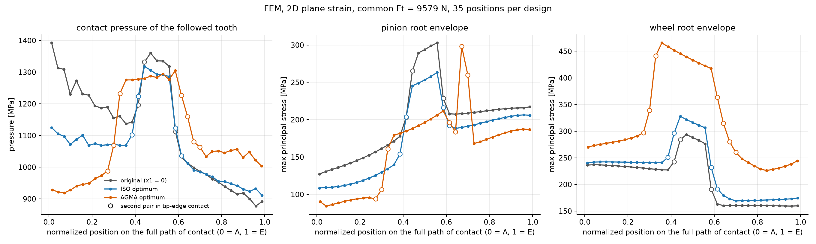
Contact pressure and root-stress envelopes along the full path of contact, 35 FEM positions per design. Open markers flag positions where a second pair is in tip-edge contact and its pressure peak distorts the neighbouring values.#
The FEM solves contact and bending in the same simulation, so each result is a complete stress state, not a local number. The first figure shows it at the middle of each path, the animation follows it along the whole path.
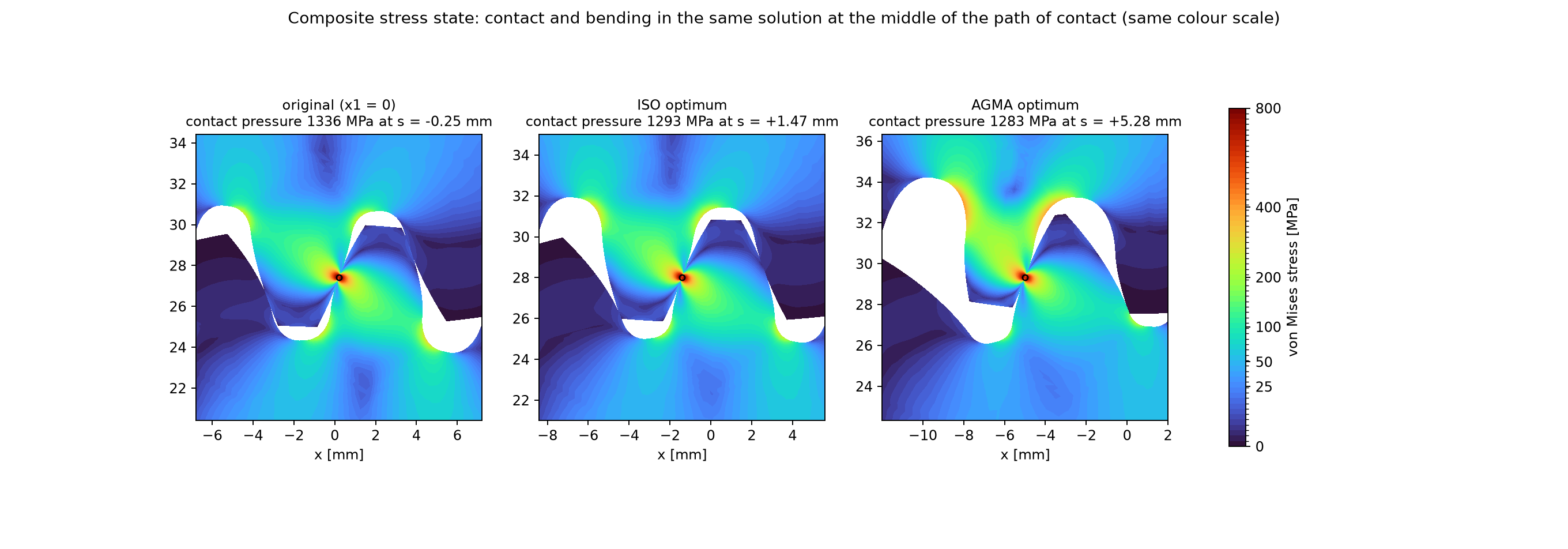
Von Mises stress at the middle of each path of contact. The colour scale is quadratic, so the root stresses stay readable next to the much larger contact peaks.#
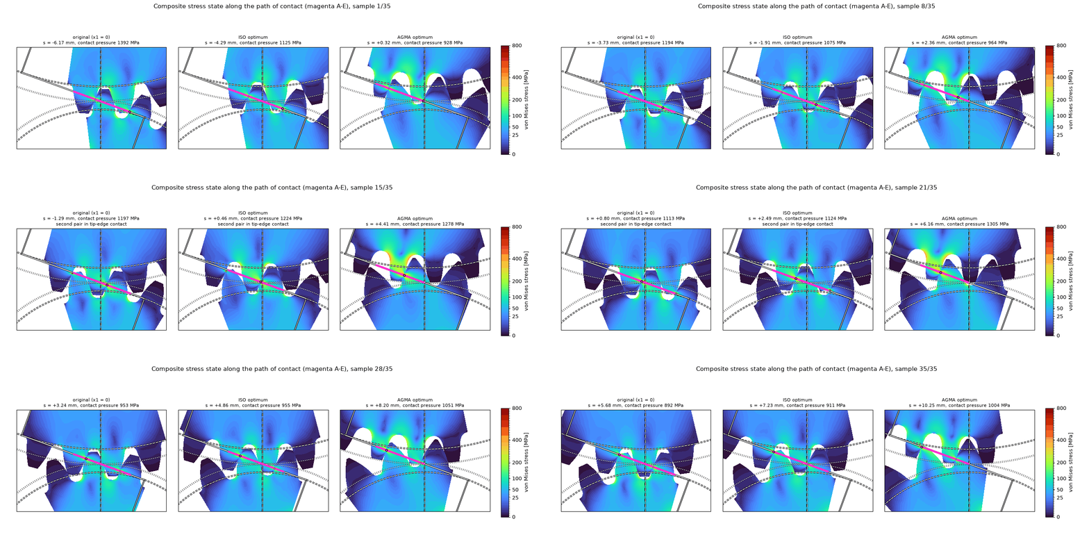
Von Mises stress as the teeth turn through the mesh, one frame per FEM position; the magenta line is the path of contact A-E, and the colour scale is the same quadratic one.#
This is a demonstration of the tools, not a research study. The FEM model is 2D plane strain without friction, no mesh-convergence study was done, and the ISO and AGMA values are factored rating stresses while the FEM values are nominal: they show trends, they do not validate the standards. Tip-edge contact where the next pair engages produces local peaks that are artifacts of the model. The ISO safety factors below 1 reflect the example loading, not a recommendation.
To reproduce it, run python docs/figures/optimization_case_study.py --stage ratings, then
--stage fem (CalculiX needed, about three hours), then --stage figures and --stage animation.
Limits#
Internal gears raise
ValueError: the geometric limits used here are those of external gears.The objective is the contact stress. Balancing the safety factors of root and flank, or the pinion against the wheel, is easy to build on top: evaluate
calculate_bending()over the feasible range yourself, as in the example above.The helpers change geometry only. A different shift also changes the dynamic factor and the load distribution, and that is already included because each candidate is evaluated with the full standard calculation.
The example 03_profile_shift_optimization.py
walks through the same idea step by step. The functions are documented in
gearbox.optimization.