
Strength theory#
Two failure mechanisms. One physical starting point. More than one way to rate them.
A tooth can survive its flank contact and still crack at the root—or the reverse. Start with what the load does to the tooth, then choose a rating method. Each guide connects the mechanics, the equations and the actual inputs and results of python-gearbox.
1 · Understand the mechanics#
No standard-specific factors yet: follow the load from a narrow contact band to the root fillet.
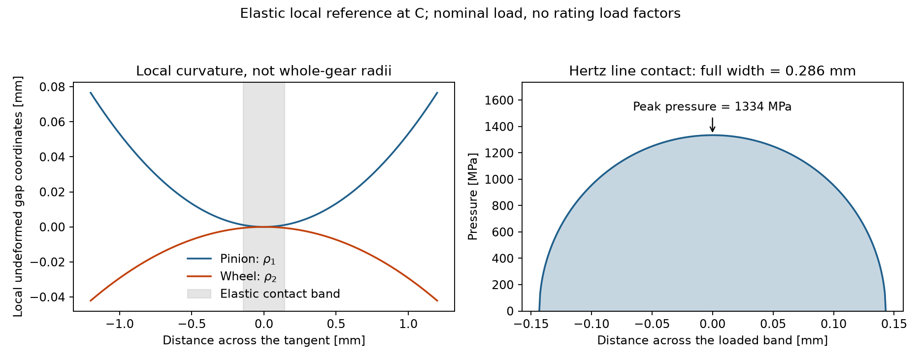
Why do curved teeth touch over a band rather than a point? Build up normal load, curvature, Hertz pressure and load sharing before evaluating surface durability.
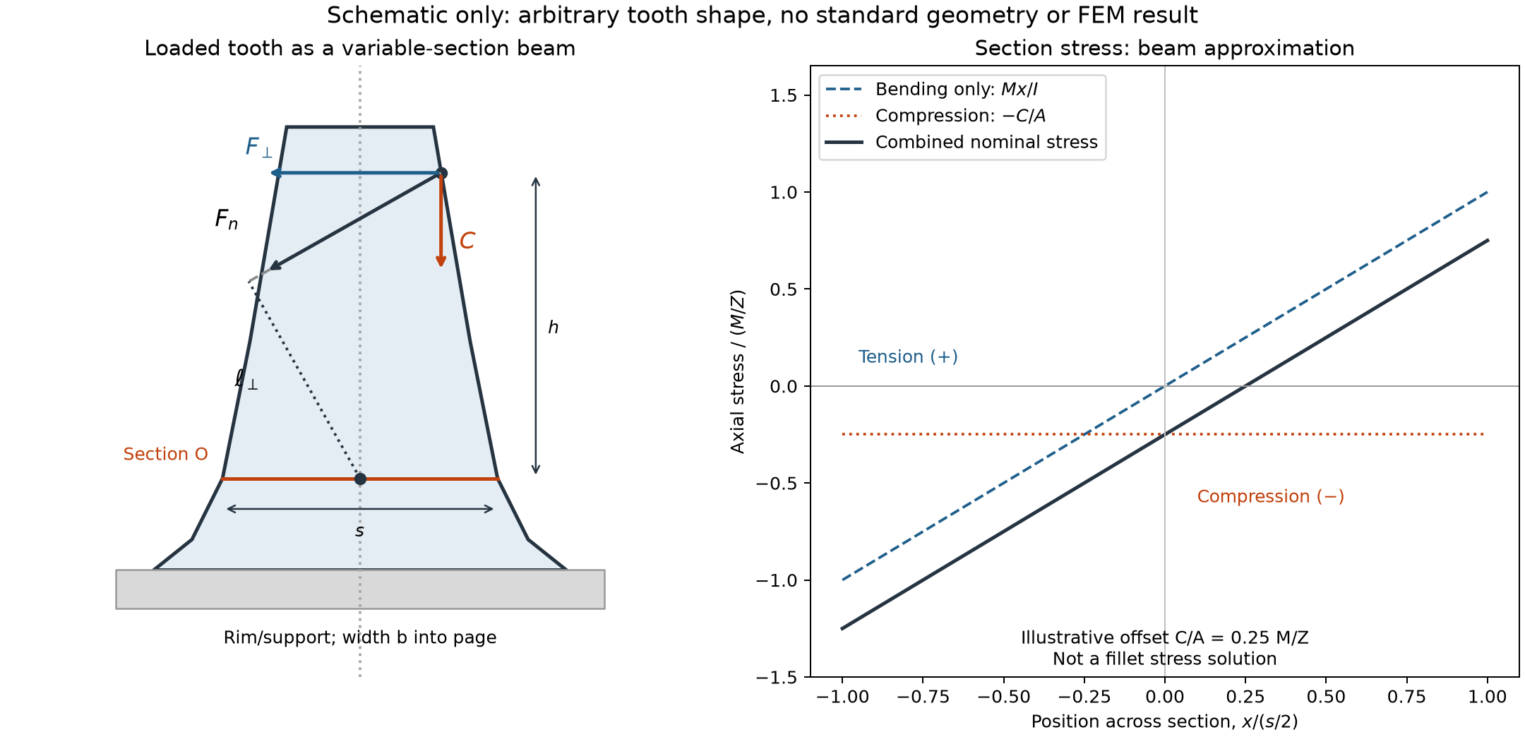
Follow the force to the critical root section. Understand bending, direct compression, fillet stress concentration and fatigue before interpreting a root safety factor.
2 · Apply a rating method#
Both families begin with the same gear pair, but organize geometry, load amplification and material resistance differently. Use each method as a coherent whole.
Begin here for the ISO route: application loads, internal dynamics, face distribution and transverse sharing. Learn why nominal torque alone is not the rated tooth load.
Turn the contact model into flank stress and compare it with the adjusted material resistance. Trace elasticity, zone factors, contact ratio and the pinion/wheel distinction.
Locate the critical root section, follow form and stress-correction factors, and distinguish the calculated tensile root stress from the permissible fatigue stress.
Take the AGMA route through applied load, geometry factors I and J, stress-cycle adjustments and material stress numbers. Keep its conventions separate from the ISO method.
3 · Interpret and cross-check#
Run the same pair through both implementations. See which inputs are shared, why stresses differ and why an ISO material limit must not silently become an AGMA allowable stress number.
Inspect contact patches and root stresses with FEM. Choose a model, check the mesh and restraint assumptions, and compare like-for-like quantities rather than isolated coloured peaks.
Tip
First visit? Read contact and bending mechanics, then choose ISO or AGMA. Checking a result? Jump straight to its method and inspect the factors before comparing safety margins.
The References remain authoritative. This guide explains the implemented subset; it is not a replacement for the standards, an engineering approval or a declaration of conformity.