
AGMA 2001-D04 and AGMA 908-B89#
AGMA separates the nominal load, the effects that amplify it and the geometry that resists it. That makes its equations compact, but not interchangeable with ISO: similar-looking factors may have different definitions and calibration.
The package namespace is agma2101 for historical reasons. The implemented rating is
AGMA 2001-D04, with geometry factors from
AGMA 908-B89. Units below are N, mm and MPa.
Find your way through the method#
If you are new to rating, read Contact mechanics: from force to surface fatigue and Bending mechanics: from tooth load to root fatigue first. The two physical failure mechanisms need separate stress checks and separate material resistance. This overview puts the whole calculation together; the following guides unpack its three main parts.
Torque, overload, dynamics, size, face distribution and rim support. Identify the assumptions and the validity checks the software does not make for you.
Follow I from curvature and sharing, and J from the generated fillet and critical root section. Understand why a tooth-count-only lookup is insufficient.
Choose traceable AGMA stress numbers, count cycles, apply life and operating adjustments, and interpret the pinion and wheel margins independently.
The calculation in one pass#
Stage |
Contact check |
Root check |
|---|---|---|
Nominal loading |
Tangential force from pinion torque |
Same nominal mesh force |
Amplification |
K_o, K_v, K_s, K_m, C_f |
K_o, K_v, K_s, K_m, individual K_B |
Geometry |
One pair factor I |
Individual J for pinion and wheel |
Applied stress |
One common contact stress |
Separate member root stresses |
Resistance |
Individual s_ac, Z_N and C_H |
Individual s_at and Y_N |
Conditions |
Divide resistance by K_T K_R |
Divide resistance by K_T K_R |
Verdict |
Individual contact stress ratios |
Individual bending stress ratios |
This is a fatigue-rating route. It does not automatically check every gear failure mode, qualify material quality or establish a safe operating envelope outside the method’s applicability.
The contact model behind the rating#
Contact mechanics: from force to surface fatigue develops the common elastic foundation. AGMA’s contact stress is Hertz-like: it depends on the square root of normal line load and reduced elastic stiffness, and increases when local curvature becomes less favourable. The standard condenses contact geometry into \(I\), rather than using ISO’s separate zone, contact-ratio and single-pair factors.
The rating has two independent sides: the applied contact stress and the material’s adjusted allowable stress. Raising a steel’s fatigue resistance does not make an otherwise unchanged elastic contact pressure disappear; it changes whether that pressure is acceptable for the required life and reliability.
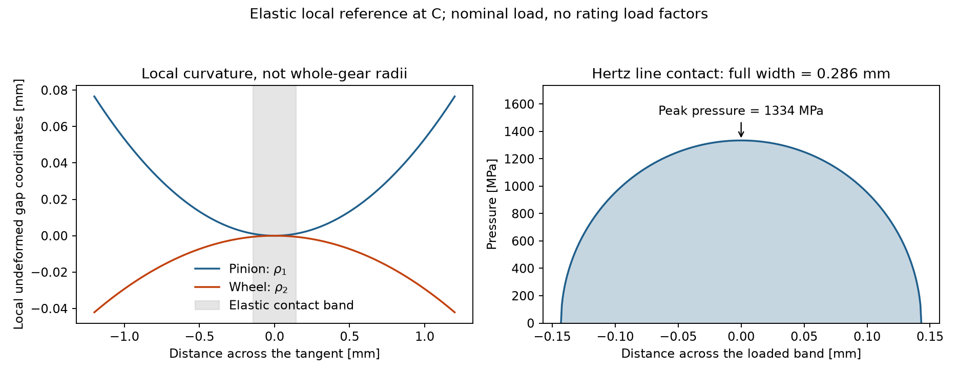
The elastic starting point: pressure varies across the contact band, so the peak is not simply force divided by an arbitrarily chosen visible flank area.#
Contact stress#
\(W_t\) is the nominal tangential load, \(F\) the narrower face width, \(d_1\) the pinion reference diameter and \(I\) the pitting geometry factor. \(C_p\) is the same elasticity coefficient as ISO’s \(Z_E\); see ISO 6336-2: surface durability (pitting). The current implementation takes \(C_f=1\).
Reading the equation physically#
\(W_t/F\) establishes a tangential line-load scale. Do not supply normal load as \(W_t\): the geometry factor already accounts for the relevant geometric conversion.
\(C_p=\sqrt{E^*/\pi}\) combines both materials. A modulus in GPa where MPa is expected would introduce a large unit error even if every other factor were correct.
\(d_1I\) is an effective geometry scale, not an actual measured contact width. Increasing \(I\), all else fixed, lowers the contact stress.
\(K_oK_vK_sK_m\) amplifies the nominal load. Each multiplier enters stress through a square root; this is different from its linear role in bending.
\(C_f=1\) is the present implementation’s surface-condition assumption. It is not a detailed rough-contact simulation and does not remove the need for appropriate material data.
For a nominal normal line load \(w\) and reduced radius \(\rho_{red}\), Hertz gives \(p_0^2=C_p^2w/\rho_{red}\). AGMA’s geometry and load factors organize that structure into a practical rating equation. An arbitrary pointwise Hertz pressure and the final AGMA rated stress need not coincide, because their load-sharing and amplification assumptions differ.
Bending stress#
For each member,
The denominator uses transverse, not normal, module: \(m_t=m_n/\cos\beta\). Each gear has its own bending geometry factor \(J\) and rim factor \(K_B\).
From beam mechanics to a rated root stress#
The basic load scale \(W_t/(F m_t)\) has stress units. J packages the generated tooth’s section and lever arm with the AGMA stress-correction and sharing treatment; it is not simply a tabulated Lewis factor. The tooth’s actual cutter and fillet data therefore matter even when module and tooth count are unchanged.
The nominal beam discussion in Bending mechanics: from tooth load to root fatigue separates bending and direct compression. Do not subtract an extra compression term or multiply by an arbitrary notch factor after using AGMA J: its construction already defines the rated root-stress convention. Likewise, the separate rim factor represents foundation flexibility, not a second fillet-concentration correction.
Because load enters linearly, a doubling of the common load multiplier doubles this root stress if all geometry and remaining factors are held fixed. A larger wheel need not be harmless: its J, rim support, material resistance and cycle count must each be checked. A common contact stress also does not imply identical bending stress or identical safety margins.
Continue with AGMA geometry: what I and J represent for the critical-section construction and AGMA resistance, life and safety for the fatigue comparison.
Influence factors#
Factor |
Meaning |
Package input or method |
|---|---|---|
\(K_o\) |
Overload |
|
\(K_v\) |
Internal dynamics |
Annex A empirical quality/speed relation |
\(K_s\) |
Size effect |
Implemented module-based interpolation; not a material-strength lookup |
\(K_m\) |
Face load distribution |
Crowning, pinion proportions, unit precision and assembly alignment |
\(K_B\) |
Thin-rim bending effect |
Backup ratio of rim thickness to tooth height |
Dynamics#
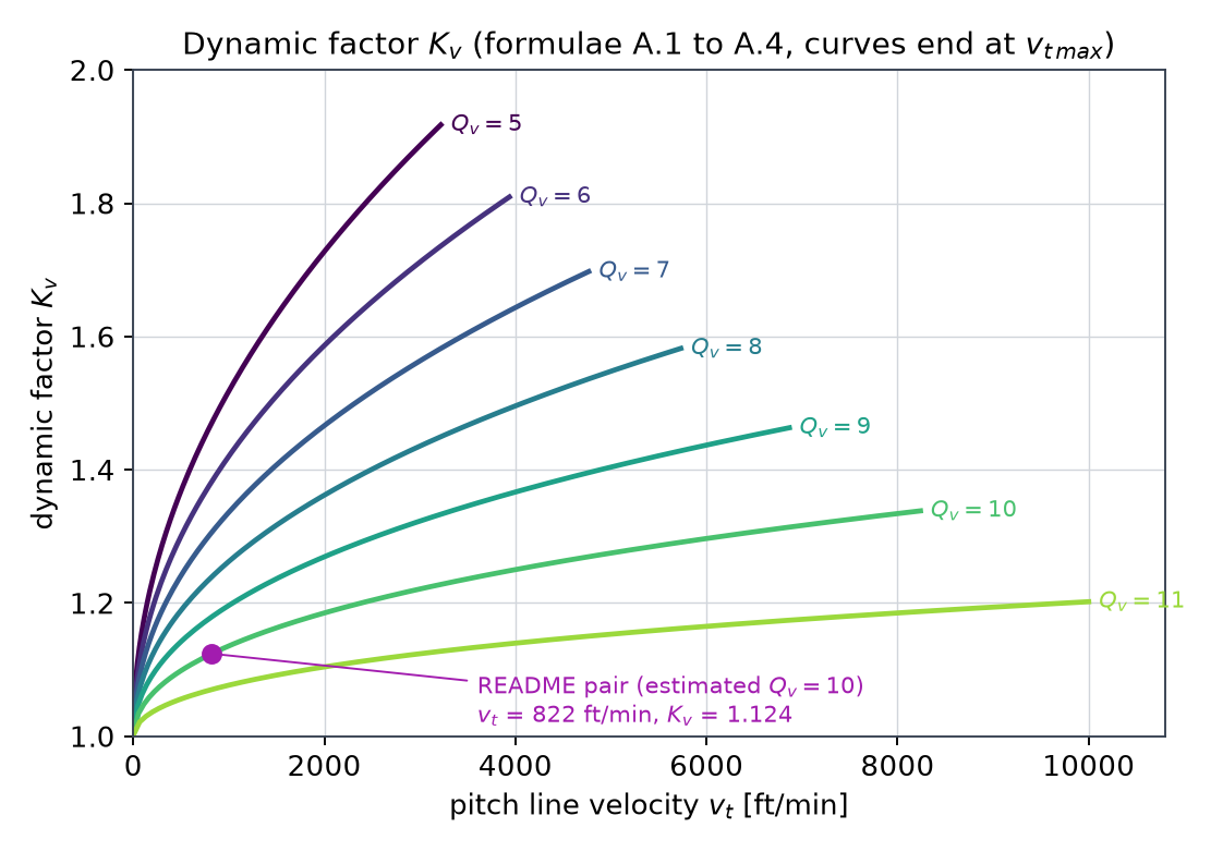
The implementation follows annex A with pitch-line velocity \(v_t\) in ft/min:
agma_quality_number supplies \(Q_v\), limited to 5–11. Higher AGMA numbers mean better quality,
unlike the ISO tolerance-class numbering. If omitted, the package estimates an equivalent number
from ISO single-pitch deviation. This is an estimate, not a formal conversion of accuracy grades.
Face load and rim effects#
Crowning controls \(C_{mc}\); width and pinion diameter control \(C_{pf}\); the shaft position controls
\(C_{pm}\); GearingType selects the unit-alignment curve \(C_{ma}\); assembly condition selects \(C_e\).
These are empirical alignment estimates, not a shaft-and-bearing finite-element solution.
For backup ratio \(m_B=t_R/h_t\), the implemented annex-B relation is
A ratio at or below 0.5 raises ValueError: a special analysis is required. With no explicit rim
thickness the code uses the radial material between root circle and bore.
Geometry factors: where the tooth enters the calculation#
\(I\) represents the curvature and sharing of the contact load. AGMA 908 evaluates curvature at the relevant load position and accounts for overlap and minimum contact-line length. Internal gearing uses the difference of curvature reciprocals instead of the sum used for external gearing.
\(J\) combines a tooth bending form with the fillet stress concentration and helical load effects. The calculation finds the critical section by tangency of a Lewis parabola to the generated root fillet; it is not simply ISO’s fixed 30-degree tangent construction. The generating cutter, profile shift and backlash allowance therefore matter.
How contact sharing enters \(I\)#
In the implemented AGMA 908 calculation, one useful form of the external pitting factor is
Here \(d\) and the curvature radii are consistently normalized by module inside the geometry calculation; \(m_N\) is a load-sharing ratio and \(C_\psi\) an overlap correction. For internal contact the sum of reciprocal positive curvature radii becomes a difference. This equation is an explanation of the implemented factor structure, not a replacement for AGMA 908’s definitions of evaluation point, overlap regimes and auxiliary dimensions.
When the face overlap exceeds one, minimum contact-line length enters the load-sharing ratio. At lower overlap, the curvature evaluation and helical correction follow a different branch. Therefore a spur approximation to \(I\) cannot simply be reused for a helical pair by replacing module and ignoring overlap. The library evaluates these branches from the actual pair geometry.
\(J\) serves a different physical purpose and must not be substituted for \(I\): increasing root thickness may improve bending while changing the contact path and curvature unfavourably. The Optimization of profile shifts chapter demonstrates precisely that trade-off.
The library calculates these factors rather than reading a single tooth-count chart. Their
implementation is exposed in gearbox.standards.agma2101._geometry; its leading underscore
means it is an inspection aid, not a stable public interface. Formula/table comparison tests live
in tests/test_agma908_tables.py.
Allowable stresses, life and safety#
The implementation returns adjusted allowable stress and a stress-ratio safety factor:
Supply AGMA stress numbers allowable_contact_stress_number and
allowable_bending_stress_number for both materials. The package does not equate them to the
ISO stress limits or infer them from hardness. Without them, stress calculations work but the
corresponding permissible stresses and safety factors are None.
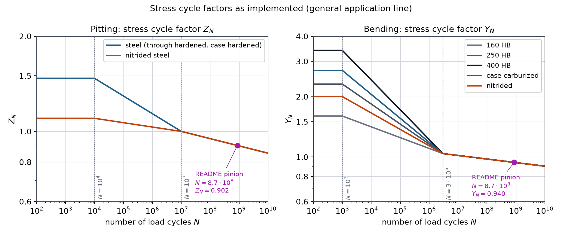
\(Z_N\) and \(Y_N\) adjust for cycles \(N=60nL_h\) using implemented steel curves.
\(C_H\) accounts for hardness pairing and surface condition; the pinion factor is 1.
\(K_T\) and \(K_R\) are supplied temperature and reliability factors. The default 1 is an assumption, not a guarantee of suitability at every temperature or reliability target.
From a contact stress to a fatigue verdict#
The stress number \(s_{ac}\) is not the measured pressure at which a particular gear immediately fails. It is an AGMA material rating input tied to reference conditions. \(Z_N\) transfers it to the required number of cycles; \(C_H\) adjusts qualifying material pairings; \(K_T\) and \(K_R\) reduce the available margin for the specified operating conditions and reliability.
The implementation’s long-life \(Z_N\) branch is \(1.4488N^{-0.023}\) above \(10^7\) cycles. Below that knee it uses material-specific steel branches and holds the low-cycle end constant. Those are the implemented general-application curves, not the unimplemented critical-service edge. A desired life outside an established validation domain deserves an engineering review, not blind extrapolation of a plotted curve.
S_H in the returned result is a stress ratio. Because elastic contact stress scales roughly
with the square root of load, a load-capacity margin would be approximately its square only if
all factors remained fixed. The implementation recalculates load-dependent factors, so this
square relationship is an interpretation aid, not an exact power-capacity calculator.
In python-gearbox#
Continue Quick start for a stress-only calculation:
from gearbox.standards import agma2101

contact = agma2101.calculate_pitting(transmission)
root = agma2101.calculate_bending(transmission)
print(f"Contact: {contact.contact_stress:.0f} MPa")
print(root.bending_stress_pinion, root.bending_stress_wheel)
print(contact.pitting_geometry_factor, root.bending_geometry_factor_pinion)
The same pair gives approximately 1846 MPa contact stress under this implementation, versus 1492 MPa for the ISO pinion result. This is not evidence that one standard is more accurate: the dynamic, geometry and allowable-stress conventions differ. Compare each stress with its own standard’s material data and acceptance criterion.
For safety calculations, create materials with independently justified AGMA stress numbers, replace
them on the gears with dataclasses.replace, and recalculate. The available reliability-factor
choices are exposed as gearbox.standards.agma2101.RELIABILITY_FACTORS.
Reconstruct the reported stresses#
A useful audit is to rebuild the final equations from the returned factors. With transmission
from Quick start, this checks arithmetic and units without reaching into private helpers:
from math import cos, isclose, radians, sqrt
from gearbox.standards import agma2101

contact = agma2101.calculate_pitting(transmission)
root = agma2101.calculate_bending(transmission)
width = transmission.net_face_width
pinion = transmission.pinion
mt = pinion.module / cos(radians(pinion.helix_angle))

load = (contact.tangential_load * contact.application_factor
        * contact.dynamic_factor * contact.size_factor
        * contact.load_distribution_factor)
reconstructed_contact = contact.elastic_coefficient * sqrt(
    load * contact.surface_condition_factor
    / (pinion.reference_diameter * width * contact.pitting_geometry_factor)
)
reconstructed_root = (
    load * root.rim_thickness_factor_pinion
    / (width * mt * root.bending_geometry_factor_pinion)
)
assert isclose(reconstructed_contact, contact.contact_stress, rel_tol=1e-12)
assert isclose(reconstructed_root, root.bending_stress_pinion, rel_tol=1e-12)
print(f"Contact: {contact.contact_stress:.1f} MPa")
print(f"Root, pinion: {root.bending_stress_pinion:.1f} MPa")
print(f"Root, wheel: {root.bending_stress_wheel:.1f} MPa")
The reference pair gives about 1845.6 MPa contact and 509.3/462.1 MPa pinion/wheel root stress. Reconstructing these equations checks the software’s reported factor combination; it is not an independent validation of every factor or a substitute for the standard.
Before accepting a rating#
Confirm the gear type and generated geometry lie within the implemented method.
Check nominal power, speed, force and units before inspecting stress amplification.
Review accuracy, speed range, support/alignment assumptions, rim thickness and surface finish.
Inspect I and both J values, including the tool and profile-shift inputs behind them.
Supply a qualified AGMA material basis; do not substitute ISO stress limits.
Check both members’ cycles, adjusted resistance and required margins.
Assess additional modes and operating conditions that this fatigue calculation does not cover.
A finite stress and a safety ratio greater than one do not waive those steps. For a controlled comparison with ISO, continue with ISO and AGMA: a controlled comparison.
Limits#
Double helical gears are rejected by the current AGMA implementation.
Internal gears support pitting, not AGMA bending: no implemented internal \(J\) is available.
Cast-iron stress-cycle factors and the critical-service edge of \(Z_N\) are not implemented.
Allowable stress-number tables are not bundled; the designer supplies those inputs.
The ISO
mesh_load_factoris not a separate multiplier in these AGMA equations.