
AGMA loads and influence factors#
The nominal torque is not the complete tooth load. AGMA separates the transmitted load from external overload, internal dynamics and imperfect load distribution. This separation helps you audit a result: if a stress looks unexpectedly high, inspect these multipliers before changing the material or the tooth geometry.
This page explains the implemented route in AGMA 2001-D04. Continue with AGMA geometry: what I and J represent for I and J, and AGMA resistance, life and safety for the resistance side of the calculation.
Start with torque, not an already amplified tooth force#
For the pinion reference diameter d₁,
Use N·mm for torque and mm for diameter to obtain N. The public calculation obtains this nominal
force from Transmission.nominal_tangential_force. Its face width F is
Transmission.net_face_width, the narrower member’s width. Do not multiply the supplied power by
an application factor and then apply the same factor again in the rating.
In the implemented contact equation the effective load product is
while bending uses
These are bookkeeping products, not measurements of a single point force. Contact stress is proportional to √W_H; bending stress is proportional to W_F at fixed geometry. Consequently a 10% increase in a common multiplier produces about 4.9% more contact stress but 10% more bending stress, provided the remaining factors stay fixed.
External overload: K_o#
Transmission.application_factor supplies K_o. It represents departures from nominal transmitted
load associated with the driving and driven machines. The package does not infer it from motor
power, machine names or a duty description.
Choose it from appropriate service evidence and the selected rating procedure. A peak overload check and a fatigue rating are not automatically the same calculation. A short severe torque transient may also require an independent yield or plastic-deformation assessment; raising a fatigue multiplier does not replace that assessment.
Internal dynamics: K_v#
Even at constant average torque, pitch/profile errors and changing mesh stiffness disturb the instantaneous load. The Annex A empirical relation represents that internal dynamic increment:
The velocity in this expression is ft/min, not m/s. The implementation converts
Transmission.pitch_line_velocity by multiplying by 196.85. Q_v is an AGMA transmission-accuracy
number; a higher number denotes better quality in this relation.
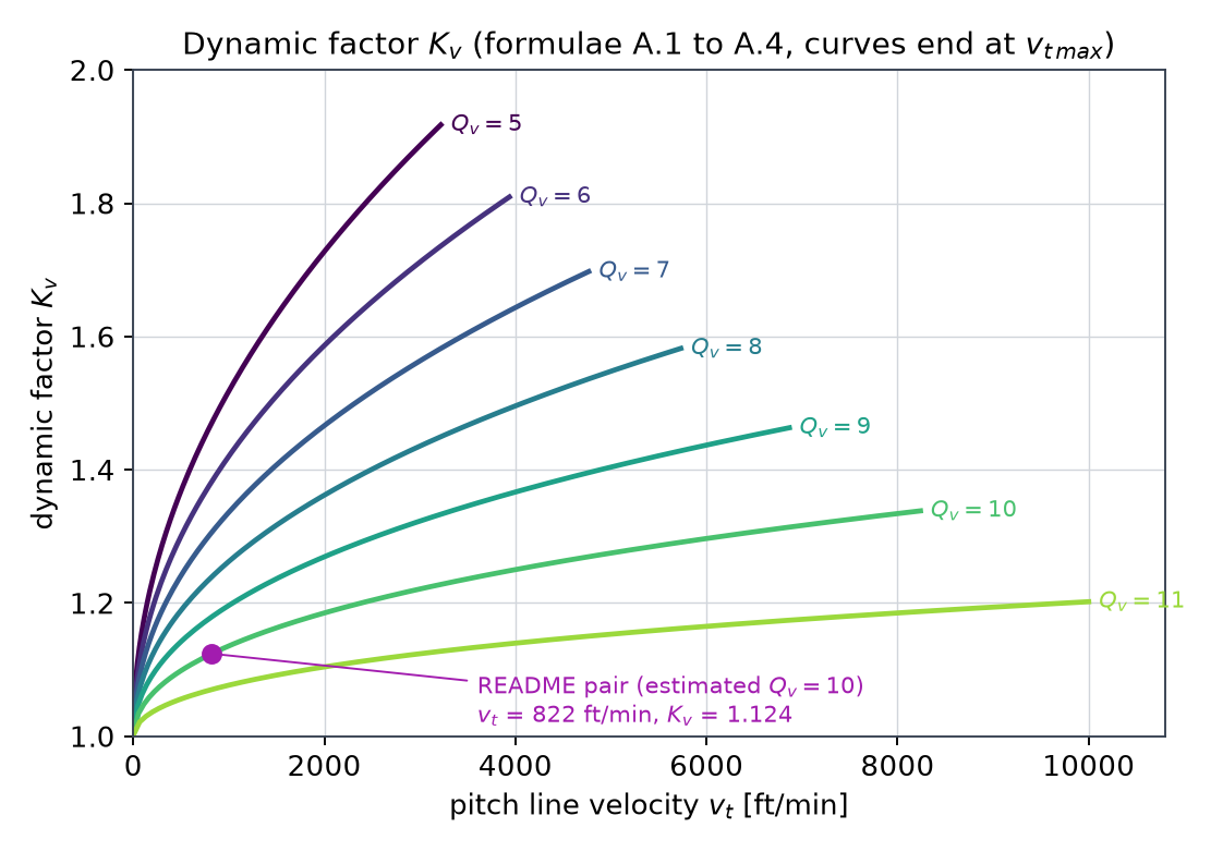
The curves describe the implemented empirical dynamics model, not a measured resonance response.#
What the quality input actually does#
An explicit
agma_quality_numberis used for the pair.If it is absent, the code estimates numbers from each gear’s ISO single-pitch deviation and uses the lower one.
The number used by the expression is limited to 5–11. Values outside that interval are clamped, not treated as independently validated extensions of the relation.
ISO accuracy grades and AGMA Q_v run in opposite directions and are not interchangeable inputs. The fallback is an estimate, not a certificate that the gear belongs to an AGMA accuracy class.
Annex A also gives a recommended velocity endpoint,
The implementation evaluates K_v without enforcing that endpoint. A finite returned value is therefore not evidence that the gear lies within the empirical curve’s recommended range. Check the range yourself. Do not use this empirical formula to clear a resonance, impact or high-speed dynamic problem that requires a measured or analytical response.
Size effect: K_s#
Larger teeth and parts may not preserve the material properties, hardening depth and stressed-volume behaviour of smaller reference specimens. That is the physical reason a size correction may be needed; it is not a change in elastic modulus.
The present software uses this module-based implementation rule:
Normal module [mm] |
Implemented K_s |
|---|---|
≤ 5 |
1.00 |
6 |
1.05 |
8 |
1.15 |
12 |
1.25 |
≥ 20 |
1.40 |
Between those points it interpolates linearly. These knots are not a tabulation prescribed by AGMA 2001-D04. Its size-factor discussion addresses material and heat-treatment suitability and does not establish this universal module table. Treat the implemented rule as a modelling assumption to review, especially for large case-hardened parts; it is not evidence of qualified case depth or through-hardening capability.
Uneven load across the face: K_m#
A wider gear does not necessarily carry the load uniformly. Shaft slope, bearing position, housing deformation, manufacturing alignment and tooth lead corrections can concentrate load at one face end. The implemented empirical face-distribution expression is
Term |
Physical role |
Software input or evaluation |
|---|---|---|
C_mc |
Effect of lead correction |
Pinion |
C_pf |
Pinion proportions |
Net width and pinion reference diameter |
C_pm |
Support-position modifier |
Pinion |
C_ma |
Expected mesh alignment |
|
C_e |
Alignment improvement |
Pinion |
The code evaluates C_pf piecewise with width in mm, and does not take F/(10d₁) below 0.05.
For C_ma it uses a width polynomial selected by GearingType. Do not use an inch-based coefficient
set with the package’s millimetre inputs. The returned result exposes the combined K_m, not all
five intermediate coefficients.
Check applicability before trusting the empirical number#
The standard’s empirical method is intended for relatively stiff arrangements and defined support and contact conditions. Its stated conditions include F/d₁ ≤ 2, face width up to 40 inches and contact across the narrower face; unusual support flexibility or excessive lead crowning requires special attention. The method is not a general solution for a momentary overload.
The package does not solve shafts, bearings or housings to establish that those conditions hold. Selecting a precision unit type is not equivalent to computing a shaft slope. For an unusually flexible or overhung arrangement, an analytical load-distribution model or suitable FEM may be necessary. See Three-dimensional FEM for capability and evidence limits.
Rim support in bending: K_B#
A thin rim changes the tooth’s foundation and can change the crack path. With radial rim thickness t_R and tooth height h_t, the backup ratio is
Each member has its own K_B. When rim_thickness is absent, the implementation uses the material
between the root circle and the bore, (root_diameter - shaft_diameter) / 2. A spoked or webbed gear
may need a more faithful structural description than that radial dimension.
At m_B ≤ 0.5 the function raises ValueError: this model calls for special analysis. Do not replace
the error by K_B = 1 or assume an arbitrarily large multiplier will adequately model rim failure.
The factor appears in bending, not as an extra multiplier of contact stress.
Surface condition: C_f#
The contact calculation currently sets C_f = 1. This is an implementation assumption. It does not simulate rough asperity contact, establish a suitable flank finish or prove freedom from micropitting, scuffing or lubrication distress. Those questions need their own evidence and methods.
Audit the public result#
After constructing transmission as in Quick start:
from gearbox.standards import agma2101

contact = agma2101.calculate_pitting(transmission)
root = agma2101.calculate_bending(transmission)
for name in ("tangential_load", "application_factor", "dynamic_factor",
             "size_factor", "load_distribution_factor"):
    print(name, getattr(contact, name))
print("Rim factors:", root.rim_thickness_factor_pinion,
      root.rim_thickness_factor_wheel)
For the reference 22/40 pair, K_v is approximately 1.124, K_s is 1 and K_m is 1.193. Those are outputs for the stated geometry and settings, not suggested universal design values. Continue with AGMA geometry: what I and J represent to see what the load is acting on.