
Bending mechanics: from tooth load to root fatigue#
A gear tooth does not need to yield visibly to break. Each engagement bends it a little; repeated engagements can initiate a crack at the root and eventually separate the tooth from the rim. The useful starting picture is a short, tapered cantilever, carrying a force on its flank. This chapter builds that picture, explains where it becomes unreliable, and connects it to the separate ISO and AGMA rating methods. It is a mechanics foundation, not a normative calculation.
1. Think of a tooth as a variable-section cantilever#
The tooth projects from the gear body, which supplies the reaction force and moment. Its thickness changes with height, and its root blends into the rim through a fillet. A beam cut at height \(y\) therefore has its own cross-sectional area \(A(y)\) and second moment of area \(I(y)\). A thick section may carry a larger moment but develop less nominal stress than a thinner section above it.
For a first spur-gear approximation, take a rectangular section of thickness \(s\) in the transverse plane and face width \(b\) into the page. This is a local idealization, not a claim that the whole involute tooth is rectangular. Tooth generation and the actual root shape matter; see Litvin and Fuentes and Gear geometry.
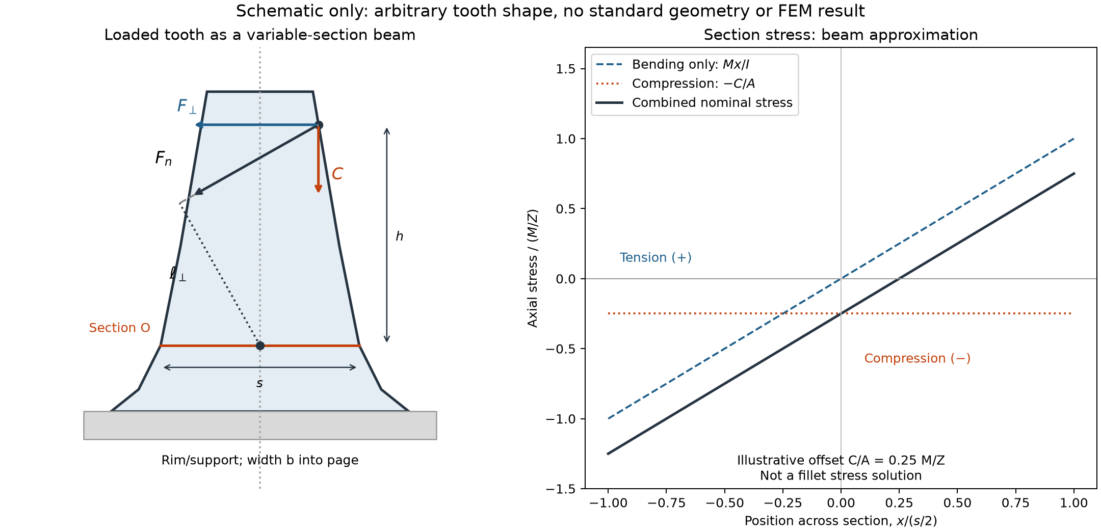
Original schematic, not an involute construction or a solver result. The section is chosen for explanation, not by an ISO or AGMA critical-section rule. The stress diagram shows the beam’s axial stress across that section; it does not resolve the fillet concentration. Width b is into the page.#
2. Resolve the force, then find its moment arm#
At a frictionless flank contact the force acts along the common normal. For a spur gear, reference-circle torque gives the nominal tangential force
Here \(d\) and \(\alpha_t\) are the reference diameter and transverse reference pressure angle. These are gear-level load conversions. Do not confuse \(F_t\) and \(F_r\) with components relative to a particular tooth section: its axis and the contact location must also be considered. For helical gearing there is an axial component and a three-dimensional contact-line distribution; the spur construction cannot simply be reused unchanged.
At the selected section, resolve the force into \(F_\perp\), transverse to the tooth axis, and \(C\), compressive along it. In the schematic, the load acts at \((e,h)\) relative to the section centroid O and has components \((-F_\perp,-C)\). With those signs the section moment magnitude is
\(\ell_\perp\) is the perpendicular distance from O to the force’s line of action, not the straight-line distance to the contact point. The approximation \(M\approx F_\perp h\) neglects the eccentric compression term; it is appropriate only when that term is small. More generally, use the cross product of position and force. A distributed contact load contributes the integral of these moments, or an equivalent resultant with the same force and moment.
The force on one tooth is also not necessarily the entire mesh force. Neighbouring tooth pairs may share it. Keep the load conversion, its distribution among teeth and its local lever arm as three separate decisions.
3. Turn the moment into nominal stress#
For the rectangular section, bending about the axis parallel to the face width gives
\(Z\) is the elastic section modulus. The extreme-fibre nominal bending stress is
With force in N and lengths in mm, the result is N/mm², or MPa. Increasing width spreads the load linearly in this uniform-width model; increasing thickness is particularly effective because it enters as \(s^2\). This comparison holds at fixed moment: changing tooth geometry may also change contact position, load sharing and the moment itself.
Direct compression shifts the whole axial stress distribution toward compression. With \(x\) measured across the section toward the tensile side and positive stress denoting tension,
The opposite edge carries \(-M/Z-C/A\). Thus a compressive contact force can still produce tensile stress at one root. The zero-stress line moves away from the centroid; under sufficiently strong compression the entire section can remain compressive. These expressions describe normal stress, not the transverse shear stress or the full multiaxial field in the fillet. They are not an instruction to subtract \(C/A\) from a standard’s already calibrated root-stress result.
4. What a Lewis model captures—and what it misses#
A Lewis-style construction uses tooth shape and an assumed loading position to turn the beam relation into a compact form, often written in the convention
Here \(Y_L\) is a dimensionless form factor defined for that convention and \(m\) is the module of the spur model. Other conventions absorb constants into the form factor: a tabulated value is meaningless without its defining equation. The construction captures the balance between lever arm and section thickness, often visualized by a parabola of equal bending strength fitted inside the tooth. It is not an exact solution of elasticity for the generated tooth.
A basic Lewis calculation assumes a prescribed static load, a simplified section, uniform loading across the width and an effectively rigid foundation. It does not by itself establish the local fillet stress, actual elastic sharing, dynamic amplification, misalignment, surface condition or fatigue strength. A short tooth also violates the slender-beam ideal: shear deformation and local load introduction can matter. Treat Lewis as a way to understand the geometry, not as a substitute for a complete rating or a converged structural analysis.
5. The fillet creates a local peak and a stress gradient#
The root fillet turns the load path into the gear body. Its changing contour raises the local elastic tensile stress above the smooth-section nominal value. A conceptual elastic concentration factor is
provided both stresses and the nominal reference are explicitly defined. A smaller fillet radius usually increases the concentration for otherwise comparable geometry. A machining or grinding notch can introduce a second, sharper concentration.
The peak is not uniform through the tooth: stress falls away from the fillet surface, creating a stress gradient. That gradient, the stressed volume, surface finish, residual stress and material notch sensitivity influence fatigue. Consequently an elastic \(K_t\) is not automatically a fatigue notch factor. Nor is it an extra multiplier to apply on top of ISO or AGMA geometry factors that already account for the root concentration. That would count the same effect twice.
6. The critical section moves with the problem#
The most highly stressed section is determined by moment, local thickness and fillet geometry together. It is not necessarily the thinnest section or the lowest point of the root. ISO and AGMA use their own constructions to identify a rating section and evaluate geometry; those constructions need not pick identical points.
As contact progresses along the flank, the moment arm changes. So does the fraction of the mesh force carried by that tooth. For an ordinary spur mesh with transverse contact ratio between one and two, part of engagement permits two pairs to carry load and part has only one. Equal sharing is an illustration, not a law: compliance, profile modifications, errors and supporting deflection set the real split. A tip load has a long lever arm but may not be the worst operating case if it carries only a small fraction of the total force. The largest root stress must be sought over the relevant mesh positions and across the face width, not inferred from lever arm alone.
7. Bending and contact respond differently to load#
At fixed geometry, load position and sharing, a linear-elastic tooth has \(M\propto F\) and hence \(\sigma_{b,\mathrm{nom}}\propto F\). Local root stresses also scale linearly while the boundary conditions and elastic contact-load distribution remain unchanged. Hertz line-contact peak pressure instead scales as \(p_{\max}\propto\sqrt{F/b}\) because its contact band widens under load; see Johnson and Contact mechanics: from force to surface fatigue.
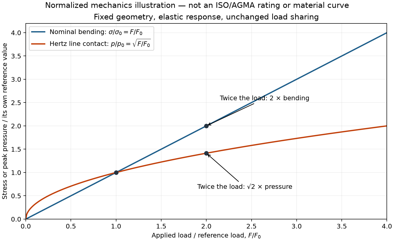
Each curve is normalized by its own nonzero reference stress or pressure at load F₀; their intersection does not mean equal dimensional stresses. These are fixed-geometry mechanics laws, not a material curve or a full rating calculation. Doubling load doubles nominal bending stress but multiplies Hertz line-contact peak pressure by √2.#
The square-root law is not universal for all contact geometries; a Hertz point contact has a different exponent. Nor must a full gear rating follow either curve exactly: load-dependent factors and changing elastic sharing can alter the trend. A bending stress safety ratio resembles a load margin only with those quantities fixed; a Hertz stress ratio corresponds approximately to its square as a load margin under the same restriction.
8. Repeated tensile stress is a fatigue question#
A tooth in a simple, one-direction gear pair is loaded and unloaded once per revolution. For constant speed \(n\) in rpm and duration \(L_h\) in hours, that gives approximately
cycles per tooth, not the mesh frequency multiplied by operating time. Multiple meshes, planetary arrangements, idlers and torque reversals require their actual loading histories. An idler tooth can load opposite flanks and experience reversed bending rather than the simple pulsating tensile history.
For a local stress cycle, define
Ideal unloading from a tensile peak to zero gives \(R=0\), not fully reversed loading (\(R=-1\)). Residual stresses and real operating histories can change that picture. An S–N relation connects a specified stress measure to cycles to failure for defined material, mean stress, surface and test conditions. A fatigue limit or a standard’s reference stress number is therefore not the yield strength, ultimate tensile strength, or a universal allowable stress for every life.
Yield strength concerns the onset of permanent deformation in a suitable static criterion; ultimate tensile strength comes from a tensile test. Neither alone supplies root-fatigue resistance. ISO and AGMA adjust their own reference material stress numbers for life and other qualifying conditions, then apply their respective acceptance and safety conventions. No material curve or numerical endurance limit is assumed here. Variable-amplitude service additionally needs a load spectrum and an appropriate fatigue-damage assessment; a single peak elastic result cannot predict an exact crack-initiation life.
9. The rim is part of the structure#
The cantilever’s clamp is only a convenient idealization. A thin rim can flex beneath the teeth, redistribute root stress and permit a crack path through the rim rather than through the tooth. Webs, spokes, hub restraint and nearby teeth also affect support compliance. Shaft and bearing deflections can concentrate load near one end of the face even when the tooth itself is unchanged.
The standards’ rim and load-distribution factors address defined parts of this problem within specified validity ranges. They do not replace a structural model of an unusually flexible rim, web or support. Clamping a finite-element tooth directly at its root may artificially suppress the very compliance under investigation. Include enough surrounding gear body and realistic restraints to represent the question being asked.
10. Compare FEM and rating stresses on equal terms#
A 2D model can resolve the actual transverse tooth contour and its root concentration economically. It still assumes a through-width behaviour: plane stress allows free out-of-plane contraction, whereas plane strain restrains out-of-plane strain and can generate out-of-plane stress. Neither assumption universally represents a real gear. Convert a 2D load consistently between force per unit width and the element formulation’s assigned thickness.
A 3D model can represent face-end effects, oblique helical contact, nonuniform loading, rim/web compliance and spatially varying restraint—if its geometry, contact and boundary conditions actually include them. It is more costly, not automatically more accurate. Both models require equilibrium checks and convergence of the chosen root-stress measure with local fillet refinement. Compare like loads, load positions, sharing, geometry and supports before comparing numerical peaks. Sharp artificial corners and point restraints may create singular peaks that do not converge.
For tensile root fatigue, the maximum principal stress and its history at the relevant fillet are a useful comparison quantity. Von Mises stress is a nonnegative distortional-energy measure, commonly used for yielding of ductile isotropic materials; it does not retain the sign of tension versus compression. In uniaxial tension they coincide, but the fillet’s multiaxial state need not be uniaxial. A von Mises contour must not silently be compared with a tensile root-fatigue allowable. A full multiaxial fatigue assessment may require more than a single principal-stress peak.
See Finite element model for the package’s numerical modelling workflow and its assumptions. No FEM solution or new solver validation is presented in this chapter.
From mechanics to a standard rating#
The next step is to keep each rating framework intact:
Continue with |
What it adds to this foundation |
|---|---|
ISO tooth-form and stress-correction treatment, load effects and permissible root stress |
|
AGMA bending geometry factor J, load and rim effects, and its own allowable-stress framework |
|
Controlled comparison of the two methods and their conventions |
The authoritative sources are ISO 6336-3, AGMA 2001-D04 and AGMA 908-B89. ISO form/stress factors and AGMA J organize geometry and concentration differently; neither their individual factors nor their reference material stress numbers are interchangeable. Use the selected standard’s definitions, applicability limits and material basis throughout. This chapter’s beam formulae explain the physical starting point; they do not modify either normative method.
The original schematic figures are reproducible from the repository root with
python docs/figures/beam_mechanics_figures.py. The generator uses only analytical normalized
curves and drawing coordinates, not a numerical gear solver.