
ISO 6336-1: load factors#
The stress formulas of ISO 6336-2 (pitting) and ISO 6336-3 (tooth root) start from the nominal tangential force \(F_t\), the force the gear pair would carry if everything were perfect. Reality adds to it: the driving and driven machines push and pull, the teeth vibrate, the load is not uniform along the face width, and the teeth of the pair do not share the load equally. Part 1 of the standard, ISO 6336-1:2019, turns each of these effects into a factor that multiplies the nominal load. This page describes those factors and how python-gearbox calculates them.
The numbers in parentheses next to the formulas, such as \((41)\), are the formula numbers of ISO 6336-1:2019. Lengths are in mm, forces in N, power in kW, speeds in rpm and deviations in µm.
Factor |
Name |
Accounts for |
In python-gearbox |
|---|---|---|---|
\(K_A\) |
application factor |
loads from the driving and driven machines |
input, |
\(K_\gamma\) |
mesh load factor |
uneven load sharing between several load paths |
input, |
\(K_v\) |
dynamic factor |
vibration of the pair, tooth errors, speed |
method B (default), method C, or a measured value |
\(K_{H\beta}\), \(K_{F\beta}\) |
face load factors |
uneven load along the face width |
method C |
\(K_{H\alpha}\), \(K_{F\alpha}\) |
transverse load factors |
uneven load between tooth pairs in contact |
method B |
The standard offers up to three methods for each factor (clause 4.1.16). Method A is a measurement or a full analysis of the real transmission. Method B is a rigorous calculation with the formulas of the standard. Method C is a simplified one, valid under stated assumptions. python-gearbox implements the methods named in the table. For method A you give the result yourself, where the library has an input for it.
Order of calculation#
The factors depend on the load, and the load depends on the factors, so they are calculated one after the other (clause 4.1.18). Each one uses the nominal load already increased by the previous ones:

Order of calculation of the load factors. Orange: the load each factor is calculated with.#
\(K_v\) is evaluated with \(F_t K_A K_\gamma\), \(K_{H\beta}\) and \(K_{F\beta}\) with \(F_t K_A K_\gamma K_v\), and \(K_{H\alpha}\) and \(K_{F\alpha}\) with \(F_t K_A K_\gamma K_v K_{H\beta}\). Note that \(K_{F\alpha}\) also uses \(K_{H\beta}\), not \(K_{F\beta}\), because it is the contact load distribution that governs the load on the tooth.
Nominal tangential force and line load#
The nominal tangential force \(F_t\) acts on the reference cylinder, in the transverse plane (clause 4.2.2). From the power \(P\) [kW] and the speed \(n\) [rpm] of the gear of reference diameter \(d\) [mm]:
with \(T\) the torque in N·m and \(v\) the speed at the reference circle in m/s. The standard also gives \(T\), \(P\), \(v\) and \(\omega\) in terms of one another (formulas 2 to 5).
Most formulas of the standard use the line load \(F_t K_A K_\gamma / b\), the load per mm of face width, as the measure of how heavily the gears are loaded. For double helical gears, \(b = 2 b_B\) (the width of both helices) and the load is assumed to be shared equally by the two (clause 4.2.1).
Application factor \(K_A\) (clause 5) adjusts the nominal load for the overloads that come from outside the gearbox: shocks from the driven machine, torque fluctuations of the engine, torsional vibration. The standard describes how to derive it from a load spectrum (method A) or asks the purchaser and manufacturer to agree on a value. It is an input of python-gearbox, 1.3 for the pair of the README.
Mesh load factor \(K_\gamma\) (clause 4.2.1) is 1.0 for a transmission with one load path, and larger than 1.0 where the load is divided between several meshes (planetary stages, split path), because the division is never perfectly even. It is also an input, 1.0 by default.
In python-gearbox,
nominal_tangential_force is \(F_t\) of formula (1),
line_load is \(F_t K_A K_\gamma / b\) and
external_load_factor is \(K_A K_\gamma\).
Dynamic factor \(K_v\)#
The teeth of a real pair do not mesh perfectly. The stiffness of the mesh changes as the number of teeth in contact changes, and pitch and profile deviations make the driven gear speed up and slow down. The pair, with its mass and its mesh stiffness, is a spring-mass system excited at the tooth meshing frequency. It answers with an extra load that depends on how close the running speed is to the natural (resonance) speed of that system.
The standard defines \(K_v\) as the ratio of the total mesh torque at the operating speed to the mesh torque with perfect gears (clause 6.1). It is never less than 1.
Method B#
Method B (clause 6.5) first finds the resonance ratio \(N\), then picks one of four speed ranges and adds up the effect of the tooth deviations.
Resonance ratio. The resonance speed of the pinion is
where \(c_{\gamma\alpha}\) is the mesh stiffness (see below) and \(m_{red}\) the reduced mass of the pair per unit face width, referred to the line of action:
For external gears the standard gives an approximation (clause 6.5.9) that ignores web and hub:
where \(\rho\) is the density, \(d_i\) the inner diameter of the rim and \(d_b\) the base diameter. For a solid disc \(1 - q^4 = 1\) (33). The running speed over the resonance speed is the resonance ratio
Speed ranges. Because damping and the stiffness of shafts and housings shift the real resonance speed, the standard widens the resonance range for safety (clause 6.5.3):
This gives four ranges: subcritical (\(N \le N_S\), where most industrial gears run), main resonance (\(N_S < N \le 1.15\)), intermediate (\(1.15 < N < 1.5\)) and supercritical (\(N \ge 1.5\)).
\(K_v\) in each range. With \(K\) and the coefficients \(C_{v1}\) to \(C_{v7}\) of table 8:
The intermediate range is a straight line between the main resonance value and the supercritical value.
Coefficients \(C_{v1}\) to \(C_{v7}\) (table 8, plotted in figure 2 of the standard) depend on the total contact ratio \(\varepsilon_\gamma = \varepsilon_\alpha + \varepsilon_\beta\):
\(1 < \varepsilon_\gamma \le 2\) |
\(\varepsilon_\gamma > 2\) |
|
|---|---|---|
\(C_{v1}\) |
0.32 |
0.32 |
\(C_{v2}\) |
0.34 |
\(0.57 / (\varepsilon_\gamma - 0.3)\) |
\(C_{v3}\) |
0.23 |
\(0.096 / (\varepsilon_\gamma - 1.56)\) |
\(C_{v4}\) |
0.90 |
\((0.57 - 0.05\,\varepsilon_\gamma) / (\varepsilon_\gamma - 1.44)\) |
\(C_{v5}\) |
0.47 |
0.47 |
\(C_{v6}\) |
0.47 |
\(0.12 / (\varepsilon_\gamma - 1.74)\) |
\(C_{v7}\) |
0.75 for \(\varepsilon_\gamma \le 1.5\); \(0.125\sin[\pi(\varepsilon_\gamma - 2)] + 0.875\) for \(1.5 < \varepsilon_\gamma \le 2\) |
\(0.125\sin[\pi(\varepsilon_\gamma - 2)] + 0.875\) for \(\varepsilon_\gamma \le 2.5\); 1.0 above |
Deviation parameters \(B_p\), \(B_f\), \(B_k\). They compare the tooth deviations with the elastic deformation of the teeth under load. The larger the deviations and the softer the load, the larger the dynamic load:
\(c'\) is the single tooth stiffness (see below). \(B_k\) accounts for the tip relief and applies only to gears of tolerance class 1 to 5 of ISO 1328-1:2013; for classes 6 to 11 it is 1.0 (footnote 4 of the standard). The effective deviations are those of the pair after running-in, that is, the initial base pitch deviation \(f_{pb}\) and profile form deviation \(f_{f\alpha}\) reduced by the running-in allowances \(y_p\) and \(y_f\):
The standard takes the larger deviation of pinion and wheel, and \(y_p = y_\alpha\) with \(y_\alpha\) from formulas (77) to (80) of clause 8.3.6.2, evaluated with \(f_{pb}\) for \(y_p\) and with \(f_{f\alpha}\) for \(y_f\):
Material |
\(y_\alpha\) [µm] |
Upper limit for \(5 < v \le 10\) m/s |
Upper limit for \(v > 10\) m/s |
|---|---|---|---|
St, St (cast), V, V (cast), GGG (perl., bai.), GTS (perl.) |
\(\dfrac{160}{\sigma_{H\,lim}} f_{pb}\) (77) |
\(12800/\sigma_{H\,lim}\) |
\(6400/\sigma_{H\,lim}\) |
GG, GGG (ferr.) |
\(0.275\,f_{pb}\) (78) |
22 |
11 |
Eh, IF, NT (nitr.), NV (nitr.), NV (nitrocar.) |
\(0.075\,f_{pb}\) (79) |
3 at all speeds |
3 at all speeds |
For pinion and wheel of different materials, \(y_\alpha\) is the mean of the two (80).
Tip relief from running-in. Without a specified tip relief \(C_a\), the relief \(C_{ay}\) produced by running-in takes its place in (17) (table 8, notes 1 and 2, figure 3):
and \(C_{ay} = 0.5\,(C_{ay1} + C_{ay2})\) if the two materials differ.
Limits. Clause 6.3 says that a calculated \(K_v < 1\) is replaced by 1. Clause 6.2.6 says that where \(K_v > 2\) outside the resonance range the value \(K_v = 2\) is used, because the model does not hold for lightly loaded gears (below 100 N/mm; below 50 N/mm there is a real risk of the flanks separating). Inside the main resonance range no limit applies, but the standard asks for a detailed analysis (method A) if \(K_v\) exceeds 2.
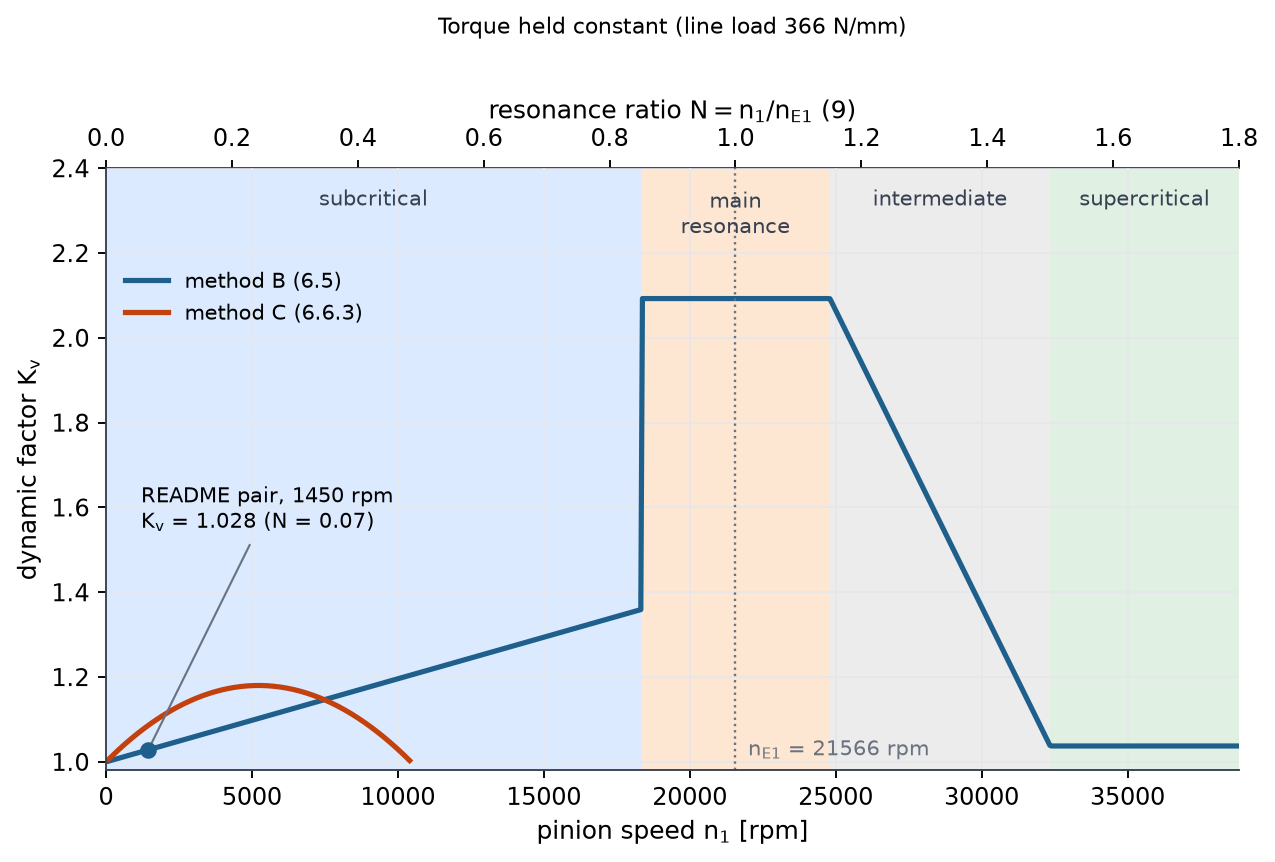
\(K_v\) of the pair of the README against the pinion speed, at constant torque. The shaded bands are the four ranges of method B. The pair runs at 1450 rpm, far below its resonance speed of about 21 600 rpm (\(N = 0.07\)), so it is in the subcritical range and the dynamic factor is small. Method C (the curve that ends at about 10 000 rpm) is only meant for the subcritical range; see below.#
Method C#
Method C (clause 6.6) replaces the resonance analysis by a formula fitted to average industrial gears. It is valid in the subcritical range, for \((v z_1/100)\sqrt{u^2/(1+u^2)} < 10\) m/s (clause 6.6.1), for external and internal spur gears and for helical gears up to \(\beta = 30°\), with \(z_1 < 50\) and solid discs or heavy rims. For spur gears and for helical gears with \(\varepsilon_\beta \ge 1\):
The line load is taken as 100 N/mm if it is lower. \(K_1\) depends on the tolerance class of the worse gear of the pair (ISO 1328-1:2013, 3 to 11) and on whether the gears are spur or helical, \(K_2\) only on that (table 11):
Class |
3 |
4 |
5 |
6 |
7 |
8 |
9 |
10 |
11 |
\(K_2\) |
|---|---|---|---|---|---|---|---|---|---|---|
\(K_1\) spur |
2.1 |
3.9 |
7.5 |
14.9 |
26.8 |
39.1 |
52.8 |
76.6 |
102.6 |
0.0193 |
\(K_1\) helical |
1.9 |
3.5 |
6.7 |
13.3 |
23.9 |
34.8 |
47.0 |
68.2 |
91.4 |
0.0087 |
For helical gears with \(\varepsilon_\beta < 1\), \(K_v\) is interpolated between the spur value \(K_{v\alpha}\) and the helical value \(K_{v\beta}\):
Method A: a measured value#
If you have measured \(K_v\) or calculated it with a dynamic model of the whole drive, give it as
Transmission.measured_dynamic_factor and it replaces the calculation. That is what the standard
asks for when a gear pair runs in its main resonance range, or when method B or C gives a value
above 2.
Mesh stiffness#
The dynamic factor and the transverse load factors need the stiffness of the teeth in contact. The standard calculates it by method B (clause 9.3), for solid-disc steel gears with a standard basic rack, and adds correction factors for other cases. Two quantities matter: the single stiffness \(c'\), the force needed to deflect one tooth pair by 1 µm over 1 mm of face width, and the mesh stiffness \(c_{\gamma\alpha}\), the average over the contact of all the pairs in mesh together.
The stiffness of the virtual spur gear in the normal section uses its number of teeth
and the single stiffness is
with the coefficients of table 13 (\(C_1\) to \(C_9\) = 0.04723, 0.15551, 0.25791, −0.00635, −0.11654, −0.00193, −0.24188, 0.00529, 0.00182), valid for the standard basic rack (\(\alpha_P = 20°\), \(h_{aP} = m_n\), \(h_{fP} = 1.2\,m_n\), \(\rho_{fP} = 0.2\,m_n\)). The correction factors are:
\(C_M = 0.8\) (85) brings the theory to the measured values for solid discs.
\(C_R\) is the gear blank factor, for the flexibility of rim and web: \(C_R = 1.0\) for a solid disc (86) and
\[ C_R = 1 + \frac{\ln(b_s/b)}{5\,e^{s_R/(5 m_n)}} \tag{87} \]with \(b_s/b\) limited to 0.2 to 1.2 and \(s_R/m_n \ge 1\). \(b_s\) is the web thickness and \(s_R\) the rim thickness.
\(C_B\) is the basic rack factor, for racks other than the standard one:
\[ C_B = \left[1.0 + 0.5\left(1.2 - \frac{h_{fP}}{m_n}\right)\right]\left[1.0 - 0.02\,(20° - \alpha_{Pn})\right] \tag{88} \]and the mean of the values of the two racks, \(C_B = 0.5\,(C_{B1} + C_{B2})\) (89), if they differ.
For other material pairs, \(c' = c'_{St/St}\,(E/E_{St})\) with \(E = 2E_1E_2/(E_1+E_2)\) and \(E_{St} = 206\,000\) MPa (90, 91).
For an internal wheel, \(z_{n2} \to \infty\) in (84) (clause 9.3.2.6 b).
For line loads below 100 N/mm the stiffness drops with the load, and
\[ c' = c'_{th}\,C_M\,C_B\,C_R \cos\beta \left(\frac{F_t K_A K_\gamma / b}{100}\right)^{0.25} \tag{92} \]
Then the mesh stiffness in the transverse direction (clause 9.3.3) is
\(c_{\gamma\alpha}\) is used for \(K_v\) and for the transverse load factors, \(c_{\gamma\beta}\) for the face load factors. For spur gears with \(\varepsilon_\alpha < 1.2\), \(c_{\gamma\alpha}\) may be up to 10 % smaller than (93).
Face load factors \(K_{H\beta}\) and \(K_{F\beta}\)#
The load along the face width is never uniform. The pinion shaft bends and twists under load, the bearings and housing deflect, and the gears carry manufacturing errors. The result is that the teeth touch each other at an angle (a mesh misalignment) and one end takes more load than the other. \(K_{H\beta}\) is the ratio of the maximum load per unit width to the mean load per unit width (clause 7.2.2):
Method C#
Method C (clause 7.5) is a simplification: only the deflection of the pinion and its shaft is calculated, the wheel is assumed stiff. The result depends on the effective equivalent misalignment \(F_{\beta y}\) and on the stiffness \(c_{\gamma\beta}\). If the contact extends over the full face width, that is, if \(F_{\beta y} c_{\gamma\beta} / (2 F_m/b) \ge 1\):
and if the load covers only part of the width, \(F_{\beta y} c_{\gamma\beta} / (2 F_m/b) < 1\):
(The contact width \(b_{cal}\) follows from (42) and (44).) For double helical gears, the smaller \(b_B\) of pinion and wheel replaces the width wherever \(b\) appears in the clause.
Effective misalignment \(F_{\beta y}\). The misalignment before running-in, \(F_{\beta x}\), is reduced by running-in, because the flanks wear until the load is spread more evenly:
The running-in allowance \(y_\beta\) [µm] and factor \(\chi_\beta\) depend on the material and on the speed (clause 7.5.3.2), with \(y_\beta \le F_{\beta x}\) and \(\chi_\beta \ge 0\):
Material |
\(y_\beta\) |
\(\chi_\beta\) |
Upper limit of \(y_\beta\) |
|---|---|---|---|
St, St (cast), V, V (cast), GGG (perl., bai.), GTS (perl.) |
\(\dfrac{320}{\sigma_{H\,lim}}F_{\beta x}\) (46) |
\(1 - \dfrac{320}{\sigma_{H\,lim}}\) (47) |
\(25600/\sigma_{H\,lim}\) for \(5 < v \le 10\) m/s; \(12800/\sigma_{H\,lim}\) for \(v > 10\) m/s |
GG, GGG (ferr.) |
\(0.55\,F_{\beta x}\) (48) |
0.45 (49) |
45 µm for \(5 < v \le 10\) m/s; 22 µm for \(v > 10\) m/s |
Eh, IF, NT (nitr.), NV (nitr.), NV (nitrocar.) |
\(0.15\,F_{\beta x}\) (50) |
0.85 (51) |
6 µm at all speeds |
For different materials, the mean of the pinion and wheel values is used (52, 53).
Initial misalignment \(F_{\beta x}\). It is the sum of the pinion and shaft deflection \(f_{sh}\) and the mesh misalignment from manufacturing \(f_{ma}\), weighted by constants \(B_1\), \(B_2\) that depend on the lead modification of the teeth (table 12), and the factor 1.33 that corrects the straight-line assumption for the deflection. Two cases:
The contact pattern is not verified (formula 54): the deflection and the manufacturing error add up.
\[ F_{\beta x} = 1.33\,B_1 f_{sh} + B_2 f_{ma}, \qquad F_{\beta x} \ge F_{\beta x\,min} \tag{54} \]The contact pattern has been checked and is favourable, for example by modifying the teeth or adjusting the bearings (formula 55): the deflection and the manufacturing error compensate each other, up to the helix slope tolerance \(f_{H\beta5}\) of class 5.
\[ F_{\beta x} = \left|1.33\,B_1 f_{sh} - f_{H\beta5}\right|, \qquad F_{\beta x} \ge F_{\beta x\,min} \tag{55} \]
Lead modification (table 12) |
\(B_1\) |
\(B_2\) |
|---|---|---|
1 None |
1.0 |
1.0 |
2 Central crowning, \(C_\beta = 0.5 f_{ma}\) |
1.0 |
0.5 |
3 Central crowning, \(C_\beta = 0.5 (f_{ma} + f_{sh})\) |
0.5 |
0.5 |
4 Helix correction |
0.1 |
1.0 |
5 Helix correction plus central crowning |
0.1 |
0.5 |
6 End relief |
0.7 |
0.7 |
Even with a perfect lead modification some misalignment remains, so \(F_{\beta x}\) is never taken below the greater of two values (formulas 57 and 58):
Mesh misalignment \(f_{ma}\) (clause 7.5.4.4) for a given accuracy class, from the helix slope deviations \(f_{H\beta1}\), \(f_{H\beta2}\) of pinion and wheel (ISO 1328-1:2013), in the average-quality-control form:
Shaft deflection \(f_{sh}\) (clause 7.5.3.5.2) is the equivalent misalignment caused by the bending and torsion of the pinion and its shaft. For spur and single helical gears:
and for double helical gears
Here \(d_1\) is the reference diameter of the pinion, \(d_{sh}\) the diameter of its shaft, \(l\) the bearing span and \(s\) the distance of the gear mid-face from the middle of the span. \(B^* = 1\) if all the power goes through a single engagement (\(B^* = 1.5\) for double helical gears). The constant \(K'\) accounts for where the pinion sits on its shaft with respect to the torqued end (figure 13), and depends on whether the pinion body stiffens the shaft (\(d_1/d_{sh} \ge 1.15\)) or not:
Arrangement (figure 13) |
\(K'\) without stiffening (\(d_1/d_{sh} < 1.15\)) |
\(K'\) with stiffening |
|---|---|---|
a) between bearings, towards the torqued end |
0.8 |
0.48 |
b) between bearings, away from the torqued end |
−0.8 |
−0.48 |
c) overhung |
1.33 |
1.33 |
d) two gears on the shaft, torque on the same side |
−0.6 |
−0.36 |
e) two gears on the shaft, torque on opposite sides |
−1.0 |
−0.6 |
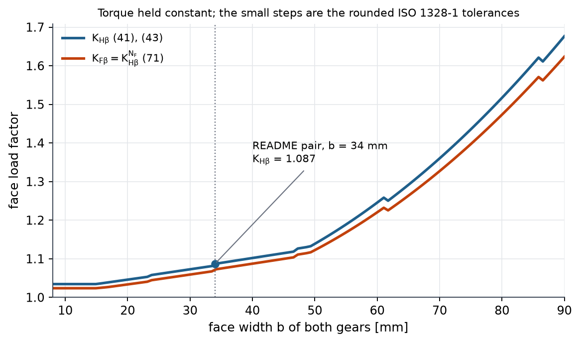
\(K_{H\beta}\) and \(K_{F\beta}\) of the pair of the README against the face width of both gears at constant torque. The pair has \(b = 34\) mm. Below about 15 mm the minimum misalignment (58) fixes the result; above it, a wider face width collects more deflection and tolerance. The small steps are the rounding of the tolerances of ISO 1328-1.#
Face load factor for the tooth root, \(K_{F\beta}\)#
\(K_{F\beta}\) (clause 7.6) is derived from \(K_{H\beta}\) with an exponent that depends on the ratio of face width \(b\) to tooth depth \(h\) (the smaller of \(b_1/h_1\) and \(b_2/h_2\); at least 3; \(b_B\) for double helical gears):
Transverse load factors \(K_{H\alpha}\) and \(K_{F\alpha}\)#
When two pairs of teeth are in contact, they should share the load. They do not do so equally: because of the base pitch deviation, the first pair to touch carries more than its share until the teeth deflect enough for the second pair to engage. \(K_{H\alpha}\) and \(K_{F\alpha}\) are the ratio of the maximum tooth load in the mesh to the load of a perfect pair. Method B (clause 8.3.2) gives, for a total contact ratio \(\varepsilon_\gamma \le 2\):
and for \(\varepsilon_\gamma > 2\):
with \(F_{tH} = F_t K_A K_\gamma K_v K_{H\beta}\), the larger base pitch deviation \(f_{pb}\) of pinion and wheel (or the larger profile form deviation, if it is greater), and the running-in allowance \(y_\alpha\) of formulas (77) to (80) above. The values are limited:
and neither is allowed below 1.0 (clauses 8.3.4 and 8.3.5). \(Z_\varepsilon\) is the contact ratio factor of ISO 6336-2 (see ISO 6336-2: surface durability (pitting)). The formulas assume that the base pitch deviations follow normal manufacturing practice and do not apply to teeth with an intentional deviation.
In python-gearbox#
The factors are calculated by the functions of
gearbox.standards.iso6336._load_factors, which
calculate_pitting() and
calculate_bending() call; you can also call them
yourself.
Function |
Gives |
|---|---|
the five factors in a |
|
\(K_v\) by the method selected in the transmission, or the measured value |
|
\(K_v\) by method B or C |
|
\(C_{ay}\) |
|
\(f_{pb}\), \(y_p\), \(f_{f\alpha}\), \(y_f\) in a |
|
\(c'\), \(c_{\gamma\alpha}\), \(c_{\gamma\beta}\) in a |
|
\(f_{sh}\) |
|
\(K_{H\beta}\), \(K_{F\beta}\) |
|
|
\(K_{H\alpha}\), \(K_{F\alpha}\) |
Which inputs feed which factor:
\(K_v\):
Transmission.dynamic_factor_method(DynamicFactorMethod.METHOD_B, the default, orMETHOD_C) andmeasured_dynamic_factor. Method B needs the tip, root and base diameters,rim_thicknessand the materialdensityandcontact_stress_limit(for \(C_{ay}\) and \(y_\alpha\)). The deviations \(f_{pb}\) (\(f_{pt}\) in the library) and \(f_{f\alpha}\) come fromGear.quality_gradethrough ISO 1328-1:2013 (tolerances). Method C only needs the quality grade (an integer from 3 to 11) and the speed.\(K_{H\beta}\), \(K_{F\beta}\):
shaft_diameter,shaft_arrangement(figure 13),bearing_span(\(l\)),offset(\(s\)),lead_modification(table 12) andfavorable_contact(formula 55 instead of 54) of the pinion, and the tolerances \(f_{H\beta}\) and \(f_{H\beta5}\) of both gears.\(c'\):
tool.dedendum_coefficientandpressure_anglefor \(C_B\),rim_thicknessandweb_thicknessfor \(C_R\) (of the pinion),Material.elastic_modulusfor (90, 91).
The example prints the factors of the pair of the README (22/40 teeth, module 2.5 mm, 34 mm, 40 kW at 1450 rpm, \(K_A = 1.3\)):
from dataclasses import replace
from gearbox import Gear, Lubricant, Material, MaterialType, ShaftArrangement, Tool, Transmission
from gearbox.enums import DynamicFactorMethod
from gearbox.standards.iso6336 import _load_factors as lf

tool = Tool(addendum_coefficient=1.0, dedendum_coefficient=1.25, root_fillet_radius_coefficient=0.38)
steel = Material(
    material_type=MaterialType.NITROCARBURIZED_STEEL,
    contact_stress_limit=1500.0, bending_stress_limit=460.0, brinell_hardness=286.7,
)
pinion = Gear(
    tool=tool, material=steel, number_of_teeth=22, module=2.5, face_width=34.0,
    quality_grade=6, surface_roughness=3.67, shaft_diameter=35.0,
    shaft_arrangement=ShaftArrangement.BETWEEN_BEARINGS_TOWARDS_TORQUED_END,
    bearing_span=60.0, offset=15.0, favorable_contact=True,
)
wheel = replace(pinion, number_of_teeth=40, shaft_diameter=50.0, offset=35.0)
t = Transmission(
    pinion=pinion, wheel=wheel, lubricant=Lubricant(kinematic_viscosity_40c=160),
    pinion_speed_rpm=1450.0, power_kw=40.0, design_life_hours=10_000.0, application_factor=1.3,
)

print(f"F_t = {t.nominal_tangential_force:.0f} N, F_t K_A K_gamma / b = {t.line_load:.1f} N/mm")
print(f"eps_alpha = {t.transverse_contact_ratio:.3f}, eps_beta = {t.overlap_ratio:.3f}")

stiffness = lf.mesh_stiffness(t)
print(f"c' = {stiffness.single_stiffness:.2f}, c_gamma_alpha = {stiffness.mesh_stiffness:.2f}, "
      f"c_gamma_beta = {stiffness.face_mesh_stiffness:.2f} N/(mm um)")

dev = lf.profile_deviations(t)
print(f"f_pb = {dev.base_pitch:.1f} um, y_p = {dev.base_pitch_allowance:.2f} um")

print(f"K_v method B = {lf.dynamic_factor_method_b(t):.3f}")
print(f"K_v method C = {lf.dynamic_factor_method_c(t):.3f}")
print(f"K_v measured = {lf.dynamic_factor(replace(t, measured_dynamic_factor=1.05)):.3f}")

factors = lf.load_factors(t)
print(f"K_Hbeta = {factors.face_load_factor_contact:.3f}, K_Fbeta = {factors.face_load_factor_root:.3f}")
print(f"K_Halpha = {factors.transverse_load_factor_contact:.3f}, "
      f"K_Falpha = {factors.transverse_load_factor_root:.3f}")
F_t = 9579 N, F_t K_A K_gamma / b = 366.3 N/mm
eps_alpha = 1.647, eps_beta = 0.000
c' = 12.84, c_gamma_alpha = 19.07, c_gamma_beta = 16.21 N/(mm um)
f_pb = 9.0 um, y_p = 0.67 um
K_v method B = 1.028
K_v method C = 1.086
K_v measured = 1.050
K_Hbeta = 1.087, K_Fbeta = 1.072
K_Halpha = 1.000, K_Falpha = 1.000
Reading the numbers: the pair is far below its resonance speed (\(N = 0.07\)), so \(K_v\) is close
to 1. The 34 mm face width and a 35 mm shaft give a pinion deflection \(f_{sh} = 6.2\) µm; with a
checked contact pattern (favorable_contact=True, formula 55) the combined misalignment is below
the minimum (58), \(F_{\beta x} = 0.5\,f_{H\beta} = 4.75\) µm, so that is the value used; running-in
removes 15 % of it (\(y_\beta = 0.71\) µm for a nitrocarburized steel), and \(K_{H\beta}\) is 1.087.
\(K_{H\alpha}\) comes out of (73) as 0.87 and is raised to the lower limit 1.0. In PittingResult the same factors are
dynamic_factor, face_load_factor and transverse_load_factor.
Limits and what is not covered#
Choices that are yours. The library does not derive \(K_A\) and \(K_\gamma\) (clauses 5 and 4.2.1): give the values. For a gear drive with several meshes (idlers, planetary stages, a wheel with two pinions) the standard asks for \(N\) to be calculated for each mesh and the least favourable taken (clause 6.5.8); python-gearbox analyses one mesh at a time and has no multi-mesh resonance analysis.
\(K_v\).
Method B is not available for an internal wheel: clause 6.5.9 gives the reduced mass of external gears only, so
dynamic_factor_method_braisesValueError. Use method C (clause 6.6.1 b) ormeasured_dynamic_factor.The tip relief \(C_a\) and the terms \(C_{f1}\), \(C_{f2}\) of formula (17) have no input. For tolerance class 5 or finer the library uses \(C_{ay}\) in place of \(C_a\) and no \(C_f\). The check on the class is made on the pinion; the pair of the README (class 6) has \(B_k = 1\). Gears of class 6 or coarser, the usual case, are not affected.
Method C is used through its formula (36) only; the graphs and tables 9 and 10 (formula 34) are not implemented. The line load is limited to at least 100 N/mm in method C, as the standard says.
Method B has no cap in the main resonance range. As the standard recommends, check by method A any result in the main resonance range or above 2.
Rimmed gears: deviation from the standard. Formula (30) has \(1/((1-q^4)\rho)\) for each gear. The code uses \((1-q^4)/\rho\), so for a gear with
rim_thicknessset the reduced mass is overestimated (by a factor of 1.5 to 2.6 for rims of 4 to 8 mm in the pair of this page) and the resonance speed underestimated. Solid discs, which includes the pair of this page, are not affected. The difference is not corrected yet.Method C below 1. Clause 6.3 replaces a calculated \(K_v < 1\) by 1. Method B does so; method C does not. It matters only above \((v z_1/100)\sqrt{u^2/(1+u^2)} \approx 5.8\) m/s, where \(K_3\) turns negative; the figure above stops the method C curve where it reaches 1.
\(K_{H\beta}\), \(K_{F\beta}\).
Methods A and B (measurement and the contact analysis of clause 7.4) are not implemented: the face load factor is always method C. It assumes a straight shaft deflection line, a stiff wheel and shaft, and its accuracy gets worse as \(K_{H\beta}\) grows (clause 7.5.1); for a pinion with \(b/d_1 > 1.5\) (through-hardened) or \(> 1.2\) (surface-hardened) the standard recommends a detailed analysis (clause 7.3.1).
Formula (56), which adds the wheel shaft, the case and the bearing displacement (\(f_{sh2}\), \(f_{ca}\), \(f_{be}\)), is not implemented. Neither is the reduced face width \(b_{(b)}\) of strongly crowned or relieved teeth (clauses 7.5.3.5.3 and 7.5.3.5.4), the choice among (62) to (65) for \(f_{ma}\) (the library uses (66)), the specified values of \(f_{sh}\) (61) and the multi-path \(B^*\) (the library takes \(B^* = 1\), or 1.5 for double helical gears).
Figure 12, which decides between (54) and (55) from the position of the contact pattern, is left to you through
favorable_contact.
\(K_{H\alpha}\), \(K_{F\alpha}\). Method B only. The permission of clause 8.3.2 to use 50 % of \(f_{pb}\) when profile modifications compensate the deflection is not applied.
Mesh stiffness. Method B only, with \(C_R\) taken from the pinion. The 10 % reduction for \(\varepsilon_\alpha < 1.2\) is applied to every pair with that contact ratio, helical ones included. The combinations that the standard marks as outside the validity of (82) (helix angle above 45°, shafts with keyed hubs) are not checked.
Double helical gears. Treated as two helical gears sharing the load equally: \(b = 2 b_B\) for the line load and for \(\sigma_{H0}\), \(b_B\) for \(\varepsilon_\beta\), for \(f_{sh}\) by formula (60) and for \(K_{F\beta}\). An unequal sharing caused by axial loads is not modelled.
Next: ISO 6336-2: surface durability (pitting) uses these factors to calculate the contact stress.