
AGMA geometry: what I and J represent#
Two pairs with the same torque, module and width need not develop the same stresses. The contact path, local curvature, root contour and load-sharing geometry matter. AGMA represents those geometric effects with I for pitting and a separate J for each member in bending.
The package calculates these factors through the analytical construction of AGMA 908-B89. It does not select a single value from a tooth-count chart. This guide explains the calculation’s structure; the standard remains the source for all auxiliary angles, lengths and applicability conditions.
I: curvature and contact-load sharing#
From Contact mechanics: from force to surface fatigue, Hertz line-contact pressure satisfies
with normal line load w. For external contact,
In the AGMA rating, I organizes the geometric conversion from tangential load and diameter to a Hertz-like stress. In the notation of the implementation, its external-gear expression is
The geometry routine normalizes d and both curvature radii by normal module. They must all use the same length normalization so I is dimensionless. Here d is the geometry construction’s operating-diameter quantity, not a new user-supplied diameter replacing the reference d₁ in the final rating equation. The symbols m_N and C_ψ denote sharing and overlap corrections, not the normal module m_n.
For an internal pair, the positive curvature magnitudes enter with a difference of reciprocals. Do not pass a negative radius to an external formula and assume that all the remaining geometry conventions will follow correctly. The implementation has an explicit internal branch.
Why the evaluation point matters#
On an involute flank the radius of curvature changes during engagement. Therefore I is not defined by two pitch-circle radii alone. The calculation constructs the operating geometry, path endpoints, base pitch and relevant load position before evaluating curvature.
For low face overlap, it uses the relevant single-contact geometry and an overlap correction. Above a face contact ratio of one, minimum total contact-line length enters the sharing calculation, and the curvature evaluation follows the corresponding branch. A helical pair cannot be reduced to the spur case simply by replacing normal module with transverse module.
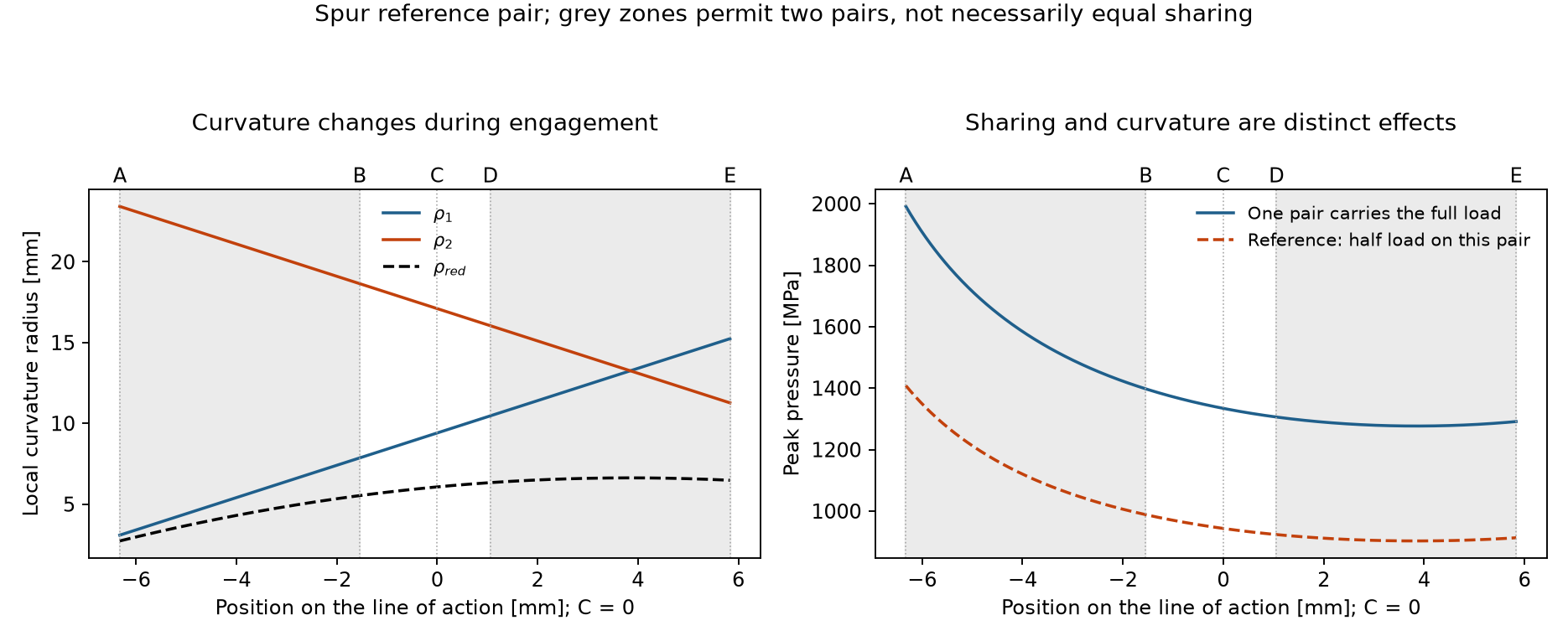
Curvature changes with mesh position. This physical illustration is not a plot of AGMA I at every position: I is a rating factor built using the standard’s evaluation and sharing rules.#
What changing I tells you#
At fixed load factors and dimensions,
A larger I reduces the rated contact stress. It does not directly indicate a stronger material, a larger root-fatigue limit or a lower bending stress. A profile-shift change can improve the contact geometry while moving one member’s root geometry in the opposite direction.
The current geometry routine uses the pinion face width in its overlap construction; the final rating uses the net, narrower face width. This implementation detail deserves attention when members have unequal widths. The equal-width reference example avoids conflating those inputs; it is not a validation of every unequal-width arrangement.
J: section strength, root concentration and sharing#
Bending mechanics: from tooth load to root fatigue gives the starting beam idea: root stress depends on moment divided by section modulus, and the local fillet adds a concentration. J combines a tooth-form contribution with the AGMA stress-correction and helical/sharing treatment.
The final rating uses
Thus a larger J reduces the calculated root stress. J is dimensionless and differs between pinion and wheel even when they use the same cutter and material.
Follow the implemented construction#
Establish the working mesh. Use operating centre distance, pressure angles, contact ratios and the mating gear to determine the load geometry.
Form the equivalent transverse/root problem. Helical geometry requires virtual-gear and load-angle quantities; it is not a tooth-count-only lookup.
Generate the root description. Cutter tooth count, addendum/dedendum convention, tip radius, tool shift, gear profile shift and backlash allowance enter the construction.
Locate the critical point. Iterate until a Lewis parabola is tangent to the generated fillet. Thickness and the load lever arm are evaluated at that point.
Apply the geometric stress correction and sharing terms. The resulting factor belongs in the AGMA rating equation as a whole.
In the implementation’s notation, the final combination has the structure
where Y is the constructed form term and K_f is the AGMA root stress-correction term. These are not interchangeable with an arbitrary Lewis table value, a measured fatigue-notch factor or ISO’s Y_F and Y_S. The internally used angles and normalized dimensions are part of their definitions.
The iterative routine can raise ArithmeticError if the critical-point construction does not
converge. That is not permission to substitute the last iterate as a valid J. Check the geometry
and the method’s applicability before attempting an alternative analysis.
Why manufacturing geometry is a strength input#
Two teeth with matching involute working flanks can have different root fillets. A different cutter tip radius, protuberance or machining notch can change the local concentration without a large change in pitch diameter or torque. The tool model must therefore represent the part being rated, not merely a convenient nominal rack.
This also explains why substituting ISO’s fixed critical-section construction into AGMA’s J is not a harmless simplification. Each method ties its geometry factor to its stress definition and material calibration. Keep the method intact.
Read the factors through the public API#
With transmission from Quick start:
from gearbox.standards import agma2101

contact = agma2101.calculate_pitting(transmission)
root = agma2101.calculate_bending(transmission)
print(f"I = {contact.pitting_geometry_factor:.6f}")
print(f"J pinion = {root.bending_geometry_factor_pinion:.6f}")
print(f"J wheel = {root.bending_geometry_factor_wheel:.6f}")
For that pair the values are approximately I = 0.094457, J₁ = 0.385744 and J₂ = 0.425112. These values include the stated generating-tool and mesh assumptions. They are not transferable to every 22/40 pair.
Scope and evidence#
External spur and single-helical pairs have both implemented I and J calculations.
Internal gearing has an implemented pitting factor but no implemented internal J. AGMA bending rejects that case rather than inventing a geometry factor.
Double-helical gears are rejected by the current AGMA route.
tests/test_agma908_tables.pycompares selected factors with reference table cases. Passing those cases is useful implementation evidence, not proof for every possible generated root.The private module
gearbox.standards.agma2101._geometryis available for inspection; its underscore-prefixed interface is not a stable public API.
Next, AGMA resistance, life and safety separates the stress imposed by this geometry from the material’s adjusted ability to withstand it.