
ISO 6336-2: surface durability (pitting)#
Two teeth touch over a narrow band. Even a moderate tangential force can produce a very high local pressure there. Repeated loading initiates surface fatigue; small fragments detach and leave pits. ISO 6336-2 turns that contact problem into a Hertz-based stress and a permissible stress adjusted for material, life and surface condition.
This page describes the implemented method, not a substitute for ISO 6336-2:2019 or a certification of a design.
From Hertz pressure to an ISO rating#
Read Contact mechanics: from force to surface fatigue first if the local contact model is unfamiliar. ISO does not solve the pressure band at every mesh position. It starts with a nominal Hertz-type expression and introduces calibrated factors for geometry, sharing and nonuniform load. The result is a rated stress to compare with ISO material resistance, not a complete pressure map.
Three groups must remain separate:
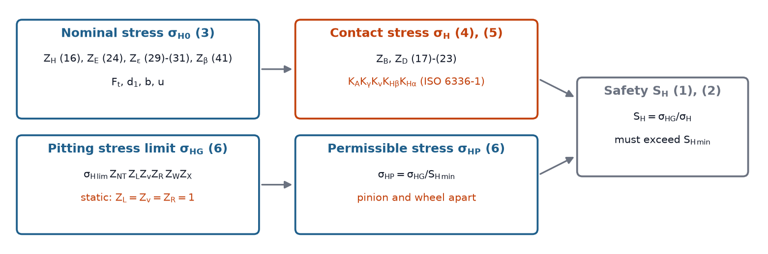
Geometry and elasticity establish nominal stress: \(Z_H\), \(Z_E\), \(Z_\varepsilon\), \(Z_\beta\).
Load amplification and distribution change the effective line load: the \(K\) factors appear under a square root.
Resistance adjustments transfer material reference data to the application: \(Z_{NT}\), \(Z_L\), \(Z_v\), \(Z_R\), \(Z_W\) and \(Z_X\) modify the permissible stress, not the applied force.
A smoother surface can improve the rating through the resistance side without changing the ideal Hertz pressure of perfectly smooth elastic cylinders. This is why interpreting every factor as an elastic stress-concentration factor would be misleading.
General equations#
For each member \(i\), the implementation evaluates
Here \(F_t\) is nominal reference-circle tangential force, \(b\) the load-carrying face width, \(d_1\) pinion reference diameter and \(u=z_2/z_1\). For double helicals \(b=2b_B\). Internal wheel quantities use signed geometry; do not replace \(u\) with its magnitude in this ISO expression. The load factors are explained in ISO 6336-1: load factors.
Geometry and elasticity#
The zone factor accounts for curvature at the working pitch point:
The elasticity factor combines the properties of both materials:
\(E_i\) is in MPa, so \(Z_E\) is in \(\sqrt{\mathrm{MPa}}\). The contact ratio factor is
The implementation uses \(Z_\beta=1/\sqrt{\cos\beta}\).
What the contact-ratio factor represents#
A larger contact ratio generally allows more contact length or more tooth pairs to carry load. \(Z_\varepsilon\) translates that sharing into the nominal rated stress. Its piecewise expression also distinguishes a spur pair, partial helical overlap and overlap of at least one axial pitch. It is not an assertion that every contacting pair always carries exactly half the load.
For the quick-start pair \(\varepsilon_\alpha\approx1.647\), giving \(Z_\varepsilon\approx0.886\). The nominal Hertz pressure at C with all load on one pair is about 1334 MPa; multiplying by this contact-ratio factor gives a lower reference level. The single-pair and load factors then increase that reference to the final rated stresses. Do not compare the final 1492 MPa pinion result directly with 1334 MPa and call the difference an error: the reference states are different.
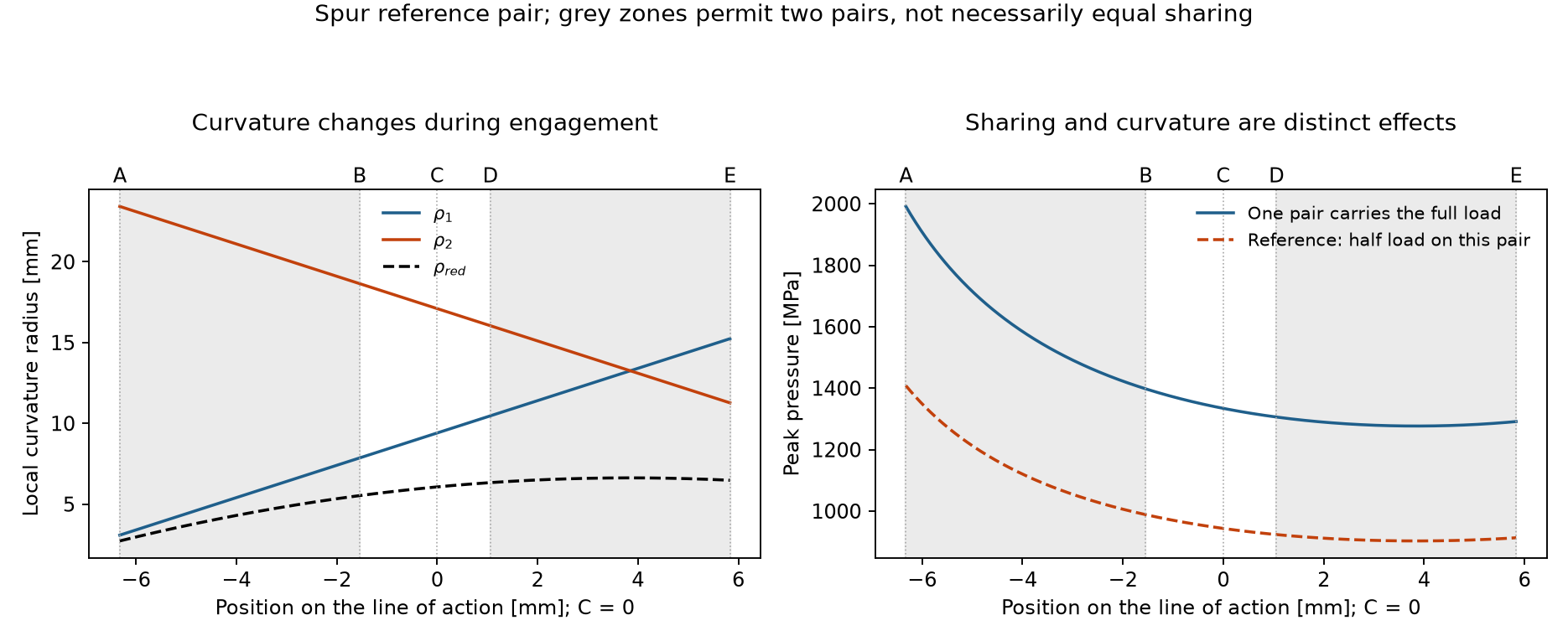
The curvature near the beginning of single-pair contact can be less favourable than at C. ISO represents this through the single-pair factors rather than a full numerical pressure sweep.#
Why two single-pair factors?#
The worst curvature is not necessarily at the pitch point. \(Z_B\) and \(Z_D\) move from the nominal pitch-point stress to the governing pinion and wheel stresses. For spur pairs the implementation uses the auxiliary quantities of clause 6.3, taking each factor no lower than 1. For an internal wheel \(Z_D=1\); for external ratios above 1.5 the wheel auxiliary quantity is taken as 1.
For helical pairs with \(\varepsilon_\beta\ge1\), both factors are
\(\sqrt{f_{ZCa}}\). FlankModification selects \(f_{ZCa}\): 1.0 for modifications optimized by 3D
analysis, 1.07 for suitable modifications, and 1.2 for unmodified flanks. Partial overlap
interpolates between the spur and helical cases. See clause 6.3, formulae (17)–(23), and table 3.
Permissible stress and safety#
The permissible stress already includes the requested minimum safety factor. Compare \(\sigma_H\le\sigma_{HP}\), or equivalently \(S_H\ge S_{H\min}\); do not apply the minimum twice.
Factor |
Physical meaning |
Inputs and implementation |
|---|---|---|
\(\sigma_{Hlim}\) |
Material contact endurance stress number |
Supplied in |
\(Z_{NT}\) |
Finite-life adjustment |
Material group, cycles \(N=60nL_h\), and |
\(Z_L\) |
Lubricant effect |
Kinematic viscosity at 40 °C, capped at 500 cSt, and weaker material limit |
\(Z_v\) |
Velocity effect |
Pitch-line velocity and weaker material limit |
\(Z_R\) |
Surface roughness effect |
Mean flank Rz and relative curvature |
\(Z_W\) |
Work hardening |
Material pairing, hardness and surface condition; generally applies to the wheel |
\(Z_X\) |
Size effect |
Fixed at 1 in the current implementation |
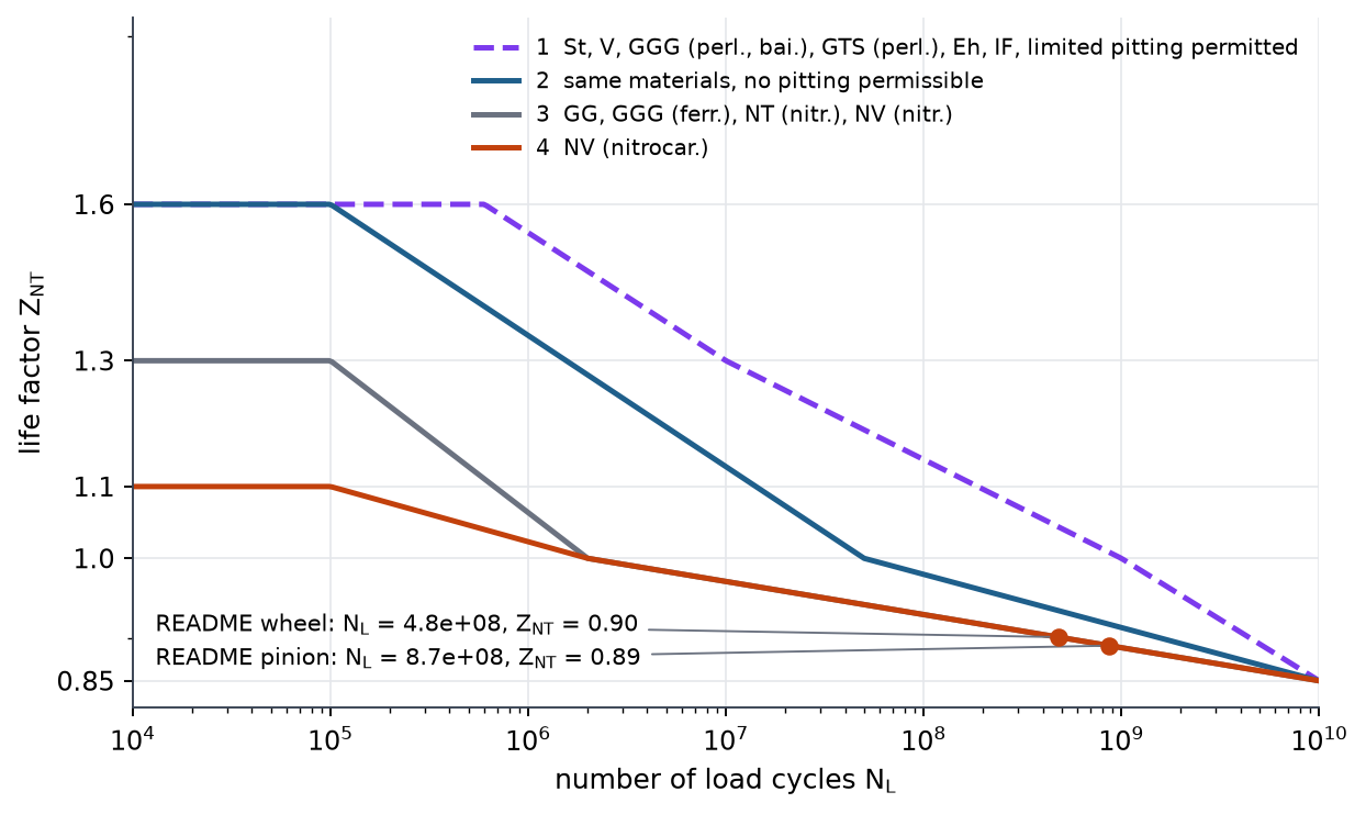
The life factor is material-dependent. Allowing limited pitting changes selected steel curves; it does not turn off the surface durability check.#
Life, lubricant, velocity, roughness and work-hardening functions are documented individually in
gearbox.standards.iso6336.pitting. The material data must match the chosen heat treatment
and quality: changing the enum alone does not supply new allowable stresses.
Life, lubrication and material pairing in practice#
Pinion and wheel have different cycle counts even when they operate for the same number of hours. The pinion usually accumulates more cycles, so its \(Z_{NT}\) can be smaller. A shared material does not imply identical permissible stress for the two members.
\(Z_L\), \(Z_v\) and \(Z_R\) are coupled empirical adjustments: viscosity is specified at 40 °C, velocity is the reference pitch-line speed, and the roughness input is Rz, not Ra. They should not be interpreted as an elastohydrodynamic film-thickness calculation. The implementation uses the weaker contact stress limit to select shared lubricant/velocity constants.
\(Z_W\) describes particular hard/soft material pairings and running-in benefits. It is not a universal bonus whenever hardness differs. The relevant material groups, hardness intervals and surface conditions must apply. \(Z_X=1\) is the current package assumption, not a general proof that size has no effect on contact fatigue.
An auditable result rather than a single number#
For the reference pair, the pinion’s \(Z_B\approx1.048\) exceeds the wheel’s \(Z_D=1\). The common load amplification includes \(K_A=1.3\), \(K_v\approx1.028\), \(K_{H\beta}\approx1.087\) and \(K_{H\alpha}=1\). Their product amplifies line load; its square root amplifies stress. Separately, the calculated pinion life factor is about 0.891. This explains why a 1500 MPa material stress number does not translate into a 1500 MPa permissible application stress.
Inspecting these groups makes a design change traceable: wider teeth reduce nominal line load, but may worsen face distribution; a higher accuracy class may reduce dynamic amplification; a new heat treatment changes the resistance model and must come with justified strength inputs.
Static calculation#
calculate_pitting(transmission, static=True) uses the horizontal initial life-factor branch,
sets \(Z_L=Z_v=Z_R=1\), and uses the static work-hardening relations. Design life is ignored for
that permissible-stress calculation. The call does not remove the calculated load factors or
replace the transmitted load with a separately specified peak load.
In python-gearbox#
Continue the pair from Quick start:
from gearbox.standards import iso6336

result = iso6336.calculate_pitting(transmission)
print(f"Pinion contact stress: {result.contact_stress_pinion:.0f} MPa")
print(f"Wheel contact stress: {result.contact_stress_wheel:.0f} MPa")
print(f"Pinion safety factor: {result.safety_factor_pinion:.2f}")
print(result.zone_factor, result.elasticity_factor, result.contact_ratio_factor)
gearbox.standards.iso6336.pitting.PittingResult preserves both stresses, both
permissible stresses, both safety factors and the intermediate factors. This makes it possible to
explain a change in result rather than treating the standard as a black box.
Scope and cautions#
Transverse contact ratios at or below 1 raise
ValueErrorin the single-pair calculation.The standard supplies no formula for \(Z_B/Z_D\) above \(\varepsilon_\alpha=2\) in the cited clause. The code does not reject that case, but it is outside its validated range.
The active-root-diameter contact-path limits are not yet implemented.
This calculation covers pitting, not scuffing, micropitting, wear or subsurface flank fracture.
A FEM pressure field and this rated stress answer different questions. See Contact analysis before comparing their peaks.