
ISO 6336-3: tooth bending strength#
ISO 6336-3:2019 answers one question: will the tooth break at the root? It computes the tensile stress in the root fillet of each gear, the stress the material can stand, and the ratio of the two. This page follows the standard clause by clause, with the formula numbers of the 2019 edition, and says for each step what python-gearbox does. The influence factors that come from part 1 (\(K_A\), \(K_\gamma\), \(K_v\), \(K_{F\beta}\), \(K_{F\alpha}\)) are explained in ISO 6336-1: load factors; the surface counterpart of this page is ISO 6336-2: surface durability (pitting).
Only method B is implemented. Method A (finite elements, strain gauges, tests of the real gear) is outside a closed-form calculation; the library’s own finite-element model is described in Finite element model.
The idea#
A tooth loaded at its flank behaves like a short, stubby cantilever beam clamped in the rim. The bending moment is largest where the tooth meets the rim, and the stress is largest on the tensile side of the root fillet. Method B reduces this to four decisions:
Where the load acts. At the outer point of single pair tooth contact (the point where the mating tooth pair last carries the load alone), because it has the longest lever arm while one pair still takes the whole force. For helical gears the same is done on the virtual spur gear of the normal section, with the normal load spread over the face width.
Which section is critical. The section whose chord joins the two points where tangents at 30° to the tooth axis touch the root fillets (60° for internal gears). Its chord \(s_{Fn}\), the fillet radius \(\rho_F\) there and the lever arm \(h_{Fe}\) of the load are the whole geometry.
A Lewis-like nominal stress. The bending stress of that beam, \(6 F h_{Fe}\cos\alpha_{Fen} / (b\,s_{Fn}^2)\), written as \(F_t/(b\,m_n)\) times a dimensionless form factor \(Y_F\).
A stress concentration on top. The fillet raises the local stress above the beam value by the stress correction factor \(Y_S\), which depends on how sharp the fillet is (\(q_s = s_{Fn}/2\rho_F\)) and on how slender the tooth is (\(L = s_{Fn}/h_{Fe}\)).
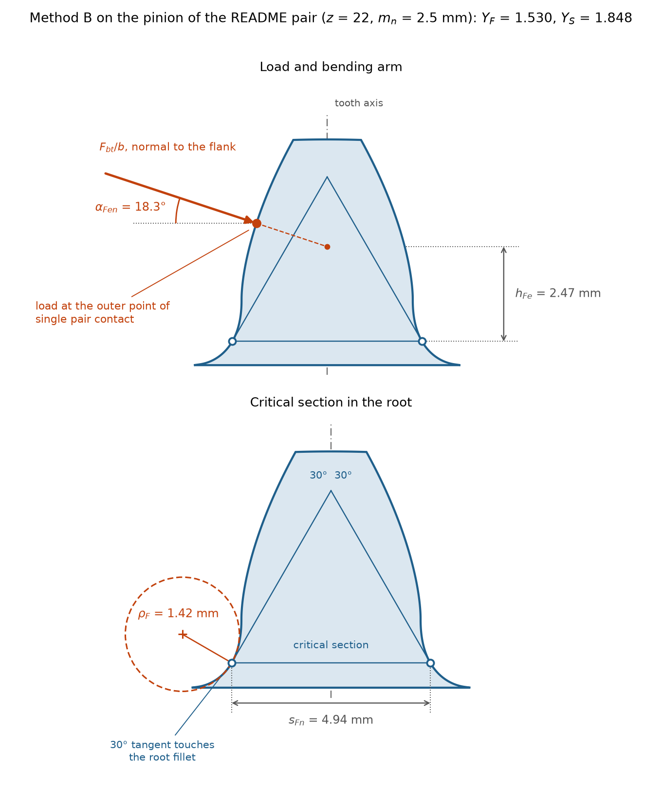
Critical section of the 22-tooth pinion of the README pair, drawn on the tooth form generated by
gearbox.profile.ToothProfile. The tangent points are found on that form; their chord differs from
the \(s_{Fn}\) of formula (30) by about 1 % (4.99 mm against 4.94 mm). The load point, \(\alpha_{Fen}\)
and \(h_{Fe}\) are the computed ISO values. Generated by docs/figures/bending_figures.py.#
Tooth root stress#
The stress at the root is the nominal stress times the load factors, formula (3), and the nominal stress is formula (4):
\(\sigma_{F0}\) is the nominal tooth root stress, the maximum local principal stress when an error-free pair carries the static nominal torque (stress ratio \(R = 0\)). It is computed separately for the pinion and the wheel: both carry the same \(F_t\), but each has its own \(Y_F\), \(Y_S\) and \(Y_B\) and possibly its own \(b\).
Symbol |
Meaning |
Where it comes from |
|---|---|---|
\(F_t\) |
nominal tangential force at the reference cylinder |
torque and reference diameter |
\(b\) |
load-bearing face width, \(b = 2 b_B\) for double helical gears |
see below |
\(m_n\) |
normal module |
gear |
\(Y_F\) |
form factor |
formula (9) |
\(Y_S\) |
stress correction factor |
formula (62) |
\(Y_\beta\) |
helix angle factor |
formula (66) |
\(Y_B\) |
rim thickness factor |
formulae (68)-(71) |
\(Y_{DT}\) |
deep tooth factor |
formulae (72)-(74) |
\(K_A K_\gamma K_v K_{F\beta} K_{F\alpha}\) |
application, mesh load, dynamic, face load and transverse load factors |
ISO 6336-1, ISO 6336-1: load factors |
Face width. \(b\) is the width at the root circle, ignoring chamfers and end rounding. When the two gears are not equally wide, the load-bearing width of the wider one is taken as the width of the narrower one plus at most one module at each end (note to formula (4)).
In python-gearbox#
calculate_bending() evaluates (3) and (4) for both
gears. \(F_t\) is nominal_tangential_force and
\(K_A K_\gamma\) is external_load_factor
(application_factor times mesh_load_factor); \(K_v\), \(K_{F\beta}\) and \(K_{F\alpha}\) come from the
ISO 6336-1 load factors of the same transmission. The face width \(b\) is the narrower width plus one
module per end, limited to the gear’s own width and doubled for double helical gears (face_width
is then the width \(b_B\) of one helix). The result gives the factors one by one, so
\(\sigma_F\) can be rebuilt by hand; with the numbers of the example below,
\(F_t/(b\,m_n) = 9579 / (34 \cdot 2.5) = 112.7\) MPa, times \(Y_F Y_S = 1.530 \cdot 1.848\), times
\(K_A K_v K_{F\beta} = 1.3 \cdot 1.028 \cdot 1.072\), gives the 457 MPa of the pinion.
Geometry of the critical section#
Virtual gear and load point#
Helical gears are treated as spur gears in the normal section. The virtual gear has the base helix angle, number of teeth and contact ratio
and the diameters of the virtual gear follow from them:
The load point is the outer point of single pair contact. On the line of action it lies one base pitch less the part of the contact ratio above one, \(p_{bn}(\varepsilon_{\alpha n} - 1)\), below the tip, which gives its diameter \(d_{en}\), pressure angle \(\alpha_{en}\), the half tooth angle \(\gamma_e\) there and the load angle \(\alpha_{Fen}\) (the angle between the load direction and the tangential direction at the tooth axis, figure above):
The number of teeth \(z\) is positive for external and negative for internal gears, which makes \(d_{en}\) negative for internal gears. If the tooth tip is rounded or chamfered, \(d_a\) in (21) is replaced by the effective tip diameter \(d_{Na}\).
Gear cut with a hob (or rack cutter)#
For an external gear generated by a rack the critical section follows from the rack’s dimensions: its dedendum \(h_{fP}\) (that is, the part of the rack that cuts the gear root), its tip radius \(\rho_{fP}\), and the residual fillet undercut \(s_{pr}\) (zero unless the gear is cut by a protuberance tool). Two auxiliary lengths and an auxiliary quantity \(G\):
The angle \(\theta\) of the tangent point on the generating trochoid is the solution of
which the standard solves by fixed-point iteration from \(\theta = \pi/6\) (about five iterations). Then
\(s_{Fn}\) is the chord between the two 30° tangent points, \(\rho_F\) the fillet radius there and \(h_{Fe}\) the distance from the chord to the point where the load line meets the tooth axis.
Gear cut with a shaper cutter#
A pinion-type shaper cutter does not produce a straight-flanked rack profile, so clause 6.2.4 constructs the generation explicitly: the gear and the cutter roll in a manufacturing mesh, the rounded tip corner \(M\) of the cutter cuts the fillet, and the tangent point is found on the envelope. Internal gears are always shaper-cut (clause 6.1 e), and clause 6.2.5 says to use the same formulae with the negative signs of internal gearing and \(\theta = 60°\).
Formulae (33) to (61)
Cutter data: number of teeth \(z_0\), profile shift \(x_0\), tip corner radius \(\rho_{a0}\), tip height \(h_{aP0}\) and residual undercut \(s_{pr}\). Tangential angle \(\theta\): 30° for external, 60° for internal gears.
Manufacturing mesh of cutter and gear:
Tip corner \(M\) of the cutter (centre of the tip rounding):
Auxiliary angle \(\psi\) by Newton iteration (two steps are generally enough; stop at \(|y/y'| < 10^{-6}\)):
Distance \(K\) from \(M\) to the contact point of the pitch circles:
Tangent point, chord, fillet radius and bending arm:
In python-gearbox#
ToothRootGeometry bundles the result for one gear, and the private helper
gearbox.standards.iso6336.bending._tooth_root_geometry(transmission, gear) computes it. It follows
the formulae above and chooses the branch from cutter_type:
Hob. Formulae (26)-(32), with the tool data of
Tool: \(h_{fP}\) isdedendum_coefficient\(\cdot\, m_n\), \(\rho_{fP}\) isroot_fillet_radius_coefficient\(\cdot\, m_n\) and \(s_{pr}\) isresidual_fillet_undercut_coefficient\(\cdot\, m_n\). \(x\) is the gear’sprofile_shift_coefficient. The iteration (29) runs nine times from \(\pi/6\) without a convergence test (the standard says about five).Shaper cutter (
Tool(cutter_type="shaper", cutter_teeth=z_0, ...)). Formulae (33)-(61): \(x_0\) isTool.profile_shift_coefficient, \(\rho_{a0}\) istool_edge_radius_coefficient\(\cdot\, m_n\) (by default the root fillet radius) and \(h_{aP0}\) is read fromdedendum_coefficient\(\cdot\, m_n\) (the tip height of the cutter equals the dedendum of the basic rack of the gear). The Newton iteration (46)-(51) stops at \(10^{-14}\) instead of \(10^{-6}\).Internal gears (
Gear.internal=Trueon the wheel) go through the shaper branch with \(\theta = 60°\), \(z_n < 0\) and the signed diameters. The cutter must have fewer teeth than the gear, and a hob raisesValueError, as clause 6.1 e) demands.
The load point uses formulae (15)-(25) with the pinion’s helix angle for both gears (they are
equal), \(\varepsilon_\alpha\) from transverse_contact_ratio
and the tip diameter \(d_a\) in place of \(d_{Na}\) (tip chamfers and rounding are not modelled).
Form factor \(Y_F\)#
Combining the beam stress at the critical section with the nominal stress of formula (4) gives formula (9):
The first factor is the Lewis form factor of this tooth: a slender tooth (large \(h_{Fe}\), small \(s_{Fn}\)) has a large \(Y_F\). \(f_\varepsilon\) is new in the 2019 edition (the standard gives it no other name than “the factor \(f_\varepsilon\)”; it “considers the influence of load distribution between the teeth in the mesh”). It matters when the virtual contact ratio \(\varepsilon_{\alpha n}\) reaches 2 or more, which happens for helical gears with high helix angle or high contact ratio: the load is then shared by more than two pairs and the root stress drops. It is one for ordinary spur gears, and formulae (10)-(14) join the cases smoothly:
Case |
\(f_\varepsilon\) |
Formula |
|---|---|---|
\(\varepsilon_\beta = 0\) and \(\varepsilon_{\alpha n} < 2\) |
\(1\) |
(10) |
\(\varepsilon_\beta = 0\) and \(\varepsilon_{\alpha n} \ge 2\) |
\(0.7\) |
(11) |
\(0 < \varepsilon_\beta < 1\) and \(\varepsilon_{\alpha n} < 2\) |
\(\left(1 - \varepsilon_\beta + \varepsilon_\beta/\varepsilon_{\alpha n}\right)^{0.5}\) |
(12) |
\(0 < \varepsilon_\beta < 1\) and \(\varepsilon_{\alpha n} \ge 2\) |
\(\left(\dfrac{1-\varepsilon_\beta}{2} + \dfrac{\varepsilon_\beta}{\varepsilon_{\alpha n}}\right)^{0.5}\) |
(13) |
\(\varepsilon_\beta \ge 1\) |
\(\varepsilon_{\alpha n}^{-0.5}\) |
(14) |
The standard states that determining \(Y_F\) by graphical means is not recommended; \(\theta\) should be iterated.
In python-gearbox, \(Y_F\) is computed per gear from its ToothRootGeometry, \(\alpha_n\) from the
transmission and \(f_\varepsilon\) from \(\varepsilon_\beta\)
(overlap_ratio, with \(b_B\) for double helical gears)
and \(\varepsilon_{\alpha n}\) of formula (17). The test \(\varepsilon_\beta = 0\) is exact, so a helical
gear is never mistaken for a spur gear.
Stress correction factor \(Y_S\)#
\(Y_S\) converts the nominal stress to the local stress in the fillet. It covers the stress amplifying effect of the change of section at the fillet and the fact that the real stress state in the critical section is more complex than the simple beam picture. Formula (62), with (63) and (64):
It is valid for \(1 \le q_s < 8\), was derived for external spur gears with 20° pressure angle, and gives approximate values for internal gears and other pressure angles (clause 7.1). Graphical determination is not appropriate. \(s_{Fn}\), \(h_{Fe}\) and \(\rho_F\) are those of the hob formulae (30)-(32) or of the shaper formulae (59)-(61).
Grinding notch. A grinding notch of depth \(t_g\) and radius \(\rho_g\) near the critical section raises the stress further. If it is at or below the point where the 30° tangent touches the fillet, \(Y_S\) is replaced by \(Y_{Sg}\), formula (65), valid for \(\sqrt{t_g/\rho_g} < 2.0\):
In python-gearbox set Gear.grinding_notch_depth (\(t_g\)) and grinding_notch_radius (\(\rho_g\)) and
\(Y_S\) is replaced by \(Y_{Sg}\) in the result; a ratio of 2.0 or more raises ValueError. The code
cannot tell where the notch sits, so give the notch only when it is near the critical section. The
range \(1 \le q_s < 8\) is not checked.
Helix angle, rim and deep tooth factors#
Helix angle factor \(Y_\beta\) (clause 8). The virtual spur gear overestimates the root stress of a helical gear, whose contact lines are oblique. With the reference helix angle \(\beta\) in degrees and the overlap ratio \(\varepsilon_\beta > 0\), formula (66):
The value 1.0 is substituted for \(\varepsilon_\beta\) when \(\varepsilon_\beta > 1\), and \(30°\) for \(\beta\) when \(\beta > 30°\). Values for \(\beta > 25°\) shall be confirmed by experience (clause 8.2).
Rim thickness factor \(Y_B\) (clause 9) derates thin-rimmed gears, where fatigue can start in the rim instead of the fillet. \(s_R\) is the rim thickness and \(h_t\) the tooth height. External gears, formulae (68) and (69):
\(s_R/h_t \le 0.5\) shall be avoided. Internal gears, formulae (70) and (71), with the module instead of the tooth height:
with \(s_R/m_n \le 1.75\) to be avoided. The scope of the standard is \(s_R > 0.5\,h_t\) (external) and \(s_R > 1.75\,m_n\) (internal).
Deep tooth factor \(Y_{DT}\) (clause 10) lowers the stress of high-precision gears with \(2 \le \varepsilon_{\alpha n} < 2.5\) that have an actual profile modification giving a trapezoidal load along the path of contact. It applies only to ISO tolerance class 4 or better, and if the classes of the two gears differ the worse one is used for both. Formulae (72) to (74):
In python-gearbox \(Y_\beta\) uses the pinion’s helix_angle and \(\varepsilon_\beta\) of the pair.
\(Y_B\) is 1 for a solid disc (rim_thickness=None) and otherwise follows the rim formulae with
Gear.rim_thickness and Gear.tooth_height; it raises ValueError below the limit of 0.5 (external)
or 1.75 (internal; the rim thickness is then mandatory). \(Y_{DT}\) uses the worse
quality_grade of the two gears; the code does not check whether a profile modification exists, so
set a quality grade above 4 if the gears have none.
Permissible stress and safety factor#
Safety factor#
The safety factor is computed separately for each gear, formulae (1) and (2), and must reach the minimum \(S_{F\min}\) agreed between manufacturer and customer (ISO 6336-1 clause 4.1.11). Since tooth breakage usually ends the life of a transmission, \(S_{F\min}\) should be larger than the minimum safety factor against pitting (clause 4):
Permissible stress, method B#
Formula (5) derives the permissible stress from the nominal stress number of the reference test gears and corrects it for the differences between that gear and the one of interest:
Symbol |
Meaning |
|---|---|
\(\sigma_{F\lim}\) |
nominal stress number (bending) from reference test gears, see ISO 6336-5 |
\(Y_{ST}\) |
stress correction factor of the reference test gear, \(Y_{ST} = 2.0\) (clause 7.4) |
\(Y_{NT}\) |
life factor for the reference test gear (clause 12) |
\(Y_{\delta\,rel\,T}\) |
relative notch sensitivity factor (clause 13) |
\(Y_{R\,rel\,T}\) |
relative surface factor (clause 14) |
\(Y_X\) |
size factor (clause 15) |
Life factor \(Y_{NT}\). It raises the permissible stress when fewer load cycles \(N_L\) than \(3 \times 10^6\) are required. Table 3 gives its value for the static load, for \(3 \times 10^6\) cycles (1.0) and for \(10^{10}\) cycles (0.85 to 1.0, the lower value for critical service). In between the standard interpolates on a log-log scale (figure 11); formulae (6) to (8) write the same thing as \(\sigma_{FP} = \sigma_{FP\,ref}\,(3\cdot10^6/N_L)^{\exp}\) with
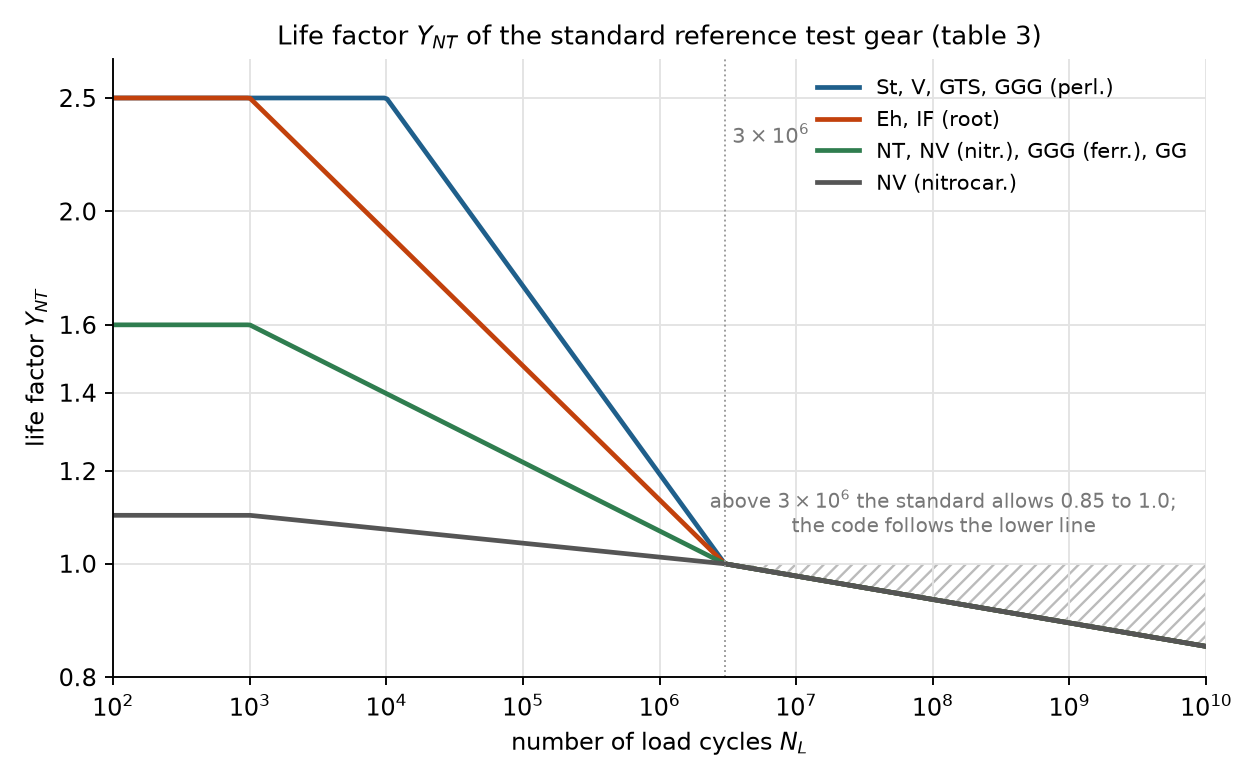
Life factor \(Y_{NT}\) as evaluated by gearbox.standards.iso6336.bending, for the four material
groups of table 3 and figure 11. Generated by docs/figures/bending_figures.py.#
The standard does not apply above stress levels permissible for \(10^3\) cycles, where the elastic limit of the tooth may be exceeded (clause 4).
Relative notch sensitivity \(Y_{\delta\,rel\,T}\) (clause 13). It says how much more or less sensitive to the sharpness of the fillet the material of the gear is than the reference gear, whose notch parameter is \(q_{sT} = 2.5\) (which corresponds to \(Y_S = 2.0\)). For the reference stress, formulae (75) to (77):
with \(\chi^*_T\) obtained from the same expression with \(q_s = q_{sT} = 2.5\). The slip layer thickness \(\rho'\) depends on the material, and on its strength, through table 4 (values between the rows may be interpolated): for example 0.3124 mm for GG with \(\sigma_B = 150\) N/mm², 0.1005 mm for NT and NV, 0.0445 mm for St with \(\sigma_S = 400\) N/mm² and 0.003 mm for Eh and IF.
For the static stress, \(Y_{\delta\,rel\,T}\) depends on \(Y_S\) instead (formulae (78) to (83)):
Material |
\(Y_{\delta\,rel\,T}\) |
Formula |
|---|---|---|
St with well-defined yield point \(\sigma_S\) |
\(\dfrac{1 + 0.93\,(Y_S - 1)\sqrt[4]{200/\sigma_S}}{1 + 0.93\sqrt[4]{200/\sigma_S}}\) |
(78) |
St with steadily increasing elongation curve, V, GGG (perl., bai.), with the 0.2 % proof stress \(\sigma_{0.2}\) |
\(\dfrac{1 + 0.82\,(Y_S - 1)\sqrt[4]{300/\sigma_{0.2}}}{1 + 0.82\sqrt[4]{300/\sigma_{0.2}}}\) |
(79) |
Eh, IF (root) |
\(0.44\,Y_S + 0.12\) |
(80) |
NT, NV |
\(0.20\,Y_S + 0.60\) |
(81) |
GTS |
\(0.075\,Y_S + 0.85\) |
(82) |
GG, GGG (ferr.) |
\(1.0\) |
(83) |
Formulae (78) and (79) hold only if the local stresses do not reach the yield point.
Relative surface factor \(Y_{R\,rel\,T}\) (clause 14). The reference gears have a root roughness \(Rz = 10\ \mu\)m; a smoother fillet gains strength and a rougher one loses it. For \(Rz < 1\ \mu\)m it is constant, formulae (84) to (86), and for \(1 \le Rz \le 40\ \mu\)m formulae (87) to (89):
Material group |
\(Rz < 1\ \mu\)m |
\(1 \le Rz \le 40\ \mu\)m |
|---|---|---|
V, GGG (perl., bai.), Eh, IF (root), GTS (perl.) |
1.12 (84) |
\(1.674 - 0.529\,(Rz + 1)^{0.1}\) (87) |
St |
1.07 (85) |
\(5.306 - 4.203\,(Rz + 1)^{0.01}\) (88) |
GG, GGG (ferr.), NT, NV |
1.025 (86) |
\(4.299 - 3.259\,(Rz + 1)^{0.005}\) (89) |
For the static stress \(Y_{R\,rel\,T} = 1.0\), formula (90).
Size factor \(Y_X\) (clause 15, table 5). Larger teeth have a larger volume of material under high stress, so the permissible stress falls with the module. For \(3 \times 10^6\) cycles:
Material |
\(m_n \le 5\) |
\(5 < m_n <\) limit |
\(m_n \ge\) limit |
|---|---|---|---|
St, V, GGG (perl., bai.), GTS (perl.) |
1.0 |
\(1.03 - 0.006\,m_n\) (\(m_n < 30\)) |
0.85 |
Eh, IF (root), NT, NV |
1.0 |
\(1.05 - 0.01\,m_n\) (\(m_n < 25\)) |
0.8 |
GG, GGG (ferr.) |
1.0 |
\(1.075 - 0.015\,m_n\) (\(m_n < 25\)) |
0.7 |
For the static stress \(Y_X = 1.0\).
Static strength#
For a load that happens a few times in the life of the gear (the standard draws the line at stresses permissible for \(10^3\) cycles), \(\sigma_{FP\,stat}\) is formula (5) with the static value of \(Y_{NT}\) (table 3: 2.5 for St, V, GGG (perl., bai.), GTS, Eh and IF; 1.6 for GG, GGG (ferr.), NT and NV (nitr.); 1.1 for NV (nitrocar.)), \(Y_{\delta\,rel\,T}\) from (78)-(83), \(Y_{R\,rel\,T} = 1.0\) and \(Y_X = 1.0\).
In python-gearbox#
\(\sigma_{F\lim}\) is Material.bending_stress_limit, \(S_{F\min}\) is
Transmission.min_safety_factor_bending, \(Y_{ST}\) is fixed at 2.0 and the number of load cycles
is \(N_L = \) design_life_hours \(\cdot\,60\cdot\) rpm of each gear (the speed of the gear, not
of the pinion). The permissible stress and the safety factor are stored as permissible_* and
safety_factor_*; permissible_* already includes \(S_{F\min}\) as in formula (5), and
\(S_F = \sigma_{FP}\,S_{F\min}/\sigma_F\).
\(Y_{NT}\) interpolates table 3 on a log-log scale between its values at the end of the static range and at \(3 \times 10^6\), and between \(3 \times 10^6\) and \(10^{10}\) it takes the lower line (0.85 at \(10^{10}\) cycles). The curve is the one of the figure above.
\(Y_{R\,rel\,T}\) uses the Rz of the fillet,
Gear.root_surface_roughness(by default the flanksurface_roughness).\(Y_X\) is piecewise linear in the module as in table 5, with the material group taken from
MaterialType.\(Y_{\delta\,rel\,T}\) follows (75)-(77) with the slip layer thickness of table 4.
calculate_bending(transmission, static=True) gives the static permissible stress: \(Y_{NT}\) is the
static value, \(Y_{R\,rel\,T} = Y_X = 1\), the design life is ignored, and \(Y_{\delta\,rel\,T}\) comes
from (78)-(83). For normalized steel (NORMALIZED_STEEL, St, formula 78) and for through-hardened
steel or pearlitic ductile iron (formula 79) it needs Material.yield_strength (\(\sigma_S\),
respectively \(\sigma_{0.2}\)), and raises ValueError without it.
In python-gearbox#
The whole calculation is one call:
from gearbox import Gear, Lubricant, Material, MaterialType, ShaftArrangement, Tool, Transmission
from gearbox.standards import iso6336
from gearbox.standards.iso6336 import bending

tool = Tool(addendum_coefficient=1.0, dedendum_coefficient=1.25, root_fillet_radius_coefficient=0.38)
steel = Material(
    material_type=MaterialType.NITROCARBURIZED_STEEL,
    contact_stress_limit=1500.0, bending_stress_limit=460.0, brinell_hardness=286.7,
)
pinion = Gear(
    tool=tool, material=steel, number_of_teeth=22, module=2.5, face_width=34.0,
    quality_grade=6, surface_roughness=3.67, shaft_diameter=35.0,
    shaft_arrangement=ShaftArrangement.BETWEEN_BEARINGS_TOWARDS_TORQUED_END,
    bearing_span=60.0, offset=15.0, favorable_contact=True,
)
wheel = Gear(
    tool=tool, material=steel, number_of_teeth=40, module=2.5, face_width=34.0,
    quality_grade=6, surface_roughness=3.67, shaft_diameter=50.0,
    shaft_arrangement=ShaftArrangement.BETWEEN_BEARINGS_TOWARDS_TORQUED_END,
    bearing_span=60.0, offset=35.0, favorable_contact=True,
)
transmission = Transmission(
    pinion=pinion, wheel=wheel, lubricant=Lubricant(kinematic_viscosity_40c=160),
    pinion_speed_rpm=1450.0, power_kw=40.0, design_life_hours=10_000.0, application_factor=1.3,
)

result = iso6336.calculate_bending(transmission)
print(f"Y_F = {result.form_factor_pinion:.3f}   Y_S = {result.stress_correction_factor_pinion:.3f}")
print(f"sigma_F = {result.tooth_root_stress_pinion:.0f} MPa   "
      f"sigma_FP = {result.permissible_tooth_root_stress_pinion:.0f} MPa")
print(f"S_F = {result.safety_factor_pinion:.2f} (pinion)   {result.safety_factor_wheel:.2f} (wheel)")

root = bending._tooth_root_geometry(transmission, pinion)   # critical section of the pinion
print(f"s_Fn = {root.tooth_root_chord:.3f} mm   rho_F = {root.root_fillet_radius:.3f} mm")
print(f"h_Fe = {root.bending_lever_arm:.3f} mm   "
      f"alpha_Fen = {degrees(root.load_angle_at_load_point):.1f} deg")

static = iso6336.calculate_bending(transmission, static=True)
print(f"static: sigma_FP = {static.permissible_tooth_root_stress_pinion:.0f} MPa, "
      f"S_F = {static.safety_factor_pinion:.2f}")
Y_F = 1.530   Y_S = 1.848
sigma_F = 457 MPa   sigma_FP = 804 MPa
S_F = 1.76 (pinion)   1.88 (wheel)
s_Fn = 4.942 mm   rho_F = 1.419 mm
h_Fe = 2.466 mm   alpha_Fen = 18.3 deg
static: sigma_FP = 981 MPa, S_F = 2.15
(Add from math import degrees at the top to run the snippet as it stands.)
_tooth_root_geometry starts with an underscore because it is an internal helper; the
ToothRootGeometry it returns is the documented
record of the critical section, and the figure of this page is drawn from it. A shaper-cut variant
of the same pair is one dataclasses.replace away:
from dataclasses import replace

shaper = replace(tool, cutter_type="shaper", cutter_teeth=25)
shaped = replace(
    transmission, pinion=replace(pinion, tool=shaper), wheel=replace(wheel, tool=shaper)
)
print(iso6336.calculate_bending(shaped).form_factor_pinion)   # 1.439 instead of 1.530
What the result contains#
BendingResult has, for each gear (_pinion and
_wheel suffixes) unless a field is shared:
Field |
Symbol |
|---|---|
|
\(\sigma_{F1}\), \(\sigma_{F2}\) (MPa) |
|
\(\sigma_{FP1}\), \(\sigma_{FP2}\) (MPa, includes \(S_{F\min}\)) |
|
\(S_{F1}\), \(S_{F2}\) |
|
\(Y_F\), \(Y_S\) (or \(Y_{Sg}\)) |
|
\(Y_\beta\), \(Y_{DT}\) (the same for both gears) |
|
\(Y_B\) |
|
\(Y_{NT}\), \(Y_{\delta\,rel\,T}\), \(Y_{R\,rel\,T}\), \(Y_X\) |
|
\(Y_{ST} = 2\) |
|
\(K_v\), \(K_{F\alpha}\), \(K_{F\beta}\) |
ToothRootGeometry has load_angle_at_load_point
(\(\alpha_{Fen}\) of formula (25) in radians), tooth_root_chord (\(s_{Fn}\)), root_fillet_radius
(\(\rho_F\)) and bending_lever_arm (\(h_{Fe}\)), the last three in mm.
Limits and what is not covered#
Scope of the standard. The formulae apply to teeth conjugate to the basic rack of ISO 53 and, for other racks, if \(\varepsilon_{\alpha n} < 2.5\); the user is cautioned to confirm results for \(\beta > 30°\) and \(\alpha_n > 25°\) by experience as by method A. The library does not check these ranges.
Method A and Annexes. Annex A (permissible stress from notched or plain test pieces), Annex B (mean stress) and the reduced endurance of reversed loading, as in idler gears (it is “taken into consideration” in \(\sigma_{F\lim}\), see ISO 6336-5), are not implemented: give a \(\sigma_{F\lim}\) that already accounts for them.
Graphical values. Figures 12 to 17 are replaced by the formulae they are consistent with. Formula (79) for a St steel without a well-defined yield point (steadily increasing elongation curve, \(\sigma_{0.2}\)) cannot be selected:
NORMALIZED_STEELalways uses (78) with the yield point.Slip layer thickness. Table 4 gives \(\rho'\) as a function of the tensile strength, yield stress or 0.2 % proof stress. The code interpolates the table with \(\sigma_{F\lim}\) in their place. For the README pinion this changes \(Y_{\delta\,rel\,T}\) by about 1 %.
Limited life. The standard interpolates between \(\sigma_{FP\,ref}\) and \(\sigma_{FP\,stat}\) with formulae (6) to (8), so the static values of \(Y_{\delta\,rel\,T}\), \(Y_{R\,rel\,T}\) and \(Y_X\) enter the curve. The code uses \(Y_{NT}\) of table 3 with the factors of the reference stress, which agrees with (6)-(8) only if both states have the same factors. For the README pinion in case-hardened steel (\(\sigma_{F\lim} = 430\) MPa) the code’s \(\sigma_{FP}\) is about 9 % above the formulae at \(10^4\) cycles, 5 % at \(10^5\) and 2 % at \(10^6\); above \(3 \times 10^6\) cycles there is no difference.
Tip rounding. \(d_a\) replaces \(d_{Na}\) in formula (21); tip chamfers and rounding are ignored, as is the \(q_s\) range of formula (62).
Tooth form of the figures and the finite-element model.
ToothProfiledraws the rack-cut tooth (including the fillet of a hob, see Gear geometry); the protuberance \(s_{pr}\) and the shaper cutter are not modelled there, though the strength calculation uses both.Internal gears. Shaper cutter only, and a rim thickness is required for \(Y_B\); the interference checks between pinion and ring need ISO 21771 and are not available.
Double helical gears. \(b = 2 b_B\), \(\varepsilon_\beta\) with \(b_B\), and the load shared equally by both helices (see
KNOWN_ISSUES.md).