
Contact mechanics: from force to surface fatigue#
A gear tooth is large compared with the patch that actually carries its load. At any instant, two curved flanks approach one another and flatten elastically over a narrow strip. The load is spread across that strip, but its pressure can still exceed a gigapascal. This is the physical starting point shared by ISO and AGMA contact ratings.
1. Convert the transmitted load into a normal load#
For a spur gear, power and speed determine torque; the reference-circle force is
Use consistent units: kW must be converted to watts, and a torque in N·mm requires a diameter in mm. The force along the common flank normal is
Here \(w\) is normal line load, in N/mm, not tangential force divided by width. For helical gears, normal/transverse projections and total contact-line length require additional geometry; the spur expression must not be applied unchanged to a 3D helical contact.
The transmission’s nominal tangential force has no application or dynamic amplification. A rating standard subsequently accounts for those effects. Keep that distinction when comparing a nominal Hertz solution, a FEM solution and a rated contact stress.
2. Replace the flanks locally by their curvature#
At a smooth contact point, the two flank sections can be approximated by their osculating circles. Their radii \(\rho_1\) and \(\rho_2\) are local curvature radii, not reference-circle radii. For external contact,
For an involute at the pitch point, \(\rho_i=r_{b,i}\tan\alpha_{wt}\). Moving a distance \(s\) from C along the line of action of an external pair gives
Thus identical force does not imply identical pressure throughout the mesh. Internal gearing has a convex flank against a concave one, requiring a curvature difference when using positive radii; ISO and AGMA encode that sign convention differently.
3. Allow both materials to deform#
The reduced elastic modulus is
Both bodies contribute. For identical materials, \(E^*=E/[2(1-\nu^2)]\), not \(E\). A larger reduced modulus creates a narrower patch and a higher pressure for the same load and geometry.
4. Find the Hertz band and its pressure#
Under elastic, frictionless line-contact assumptions, the contact half-width \(a_H\) and maximum pressure \(p_0\) are
Across the band, coordinate \(\xi\) is perpendicular to the contact line:
Integrating the semi-elliptical distribution gives \(w=\pi a_Hp_0/2\). This provides a useful consistency check on load, width and peak pressure. See Johnson.
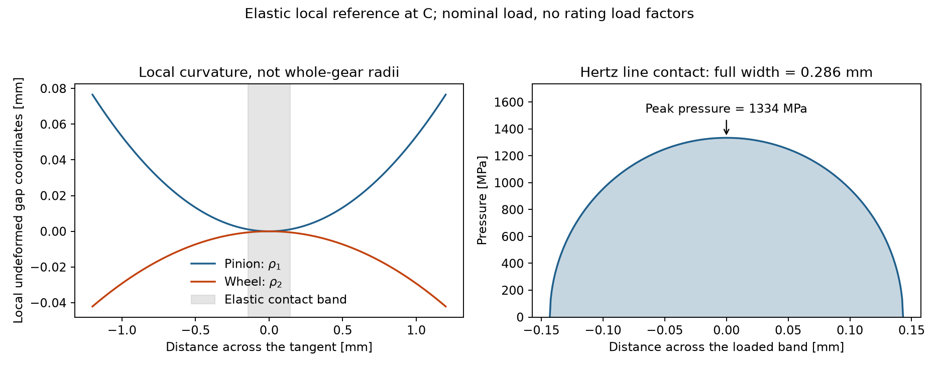
Local reference for the quick-start spur pair at C. The curvature sketch shows undeformed surfaces; the shaded band indicates the scale of the elastic contact region, not interpenetration. The example uses nominal force, without the standards’ load amplification factors.#
The formula immediately explains several design trends:
Change, all else held fixed |
Peak pressure |
Band half-width |
|---|---|---|
Double line load \(w\) |
Multiplied by \(\sqrt2\) |
Multiplied by \(\sqrt2\) |
Double reduced radius \(\rho_{red}\) |
Divided by \(\sqrt2\) |
Multiplied by \(\sqrt2\) |
Double reduced modulus \(E^*\) |
Multiplied by \(\sqrt2\) |
Divided by \(\sqrt2\) |
A load factor of 1.4 therefore does not multiply contact stress by 1.4: inside a Hertz-type rating it contributes \(\sqrt{1.4}\). Bending stress, by contrast, is nominally linear in load.
5. Follow a tooth through engagement#
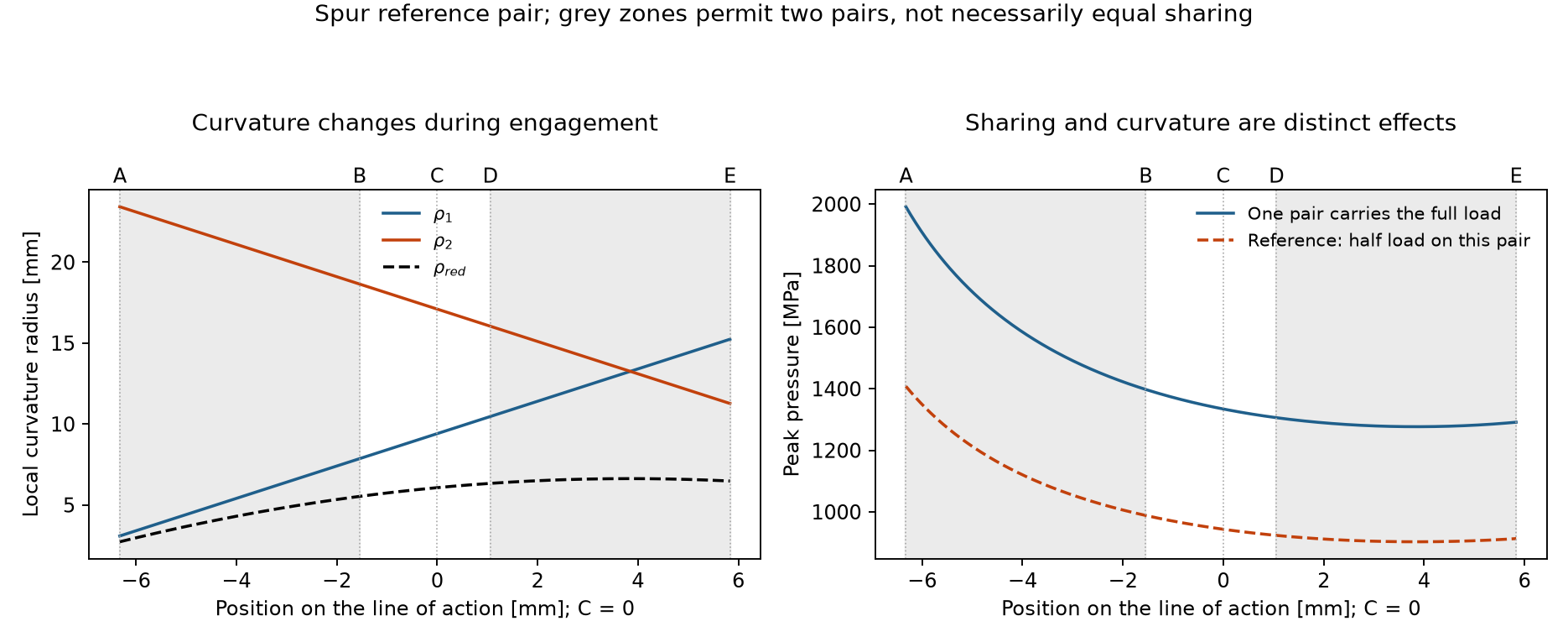
Changing curvature and changing load sharing are separate effects. The half-load curve is an illustrative equal-sharing reference, not the predicted sharing of an elastic gear pair.#
For ordinary spur pairs with contact ratio between 1 and 2, A–B and D–E allow two tooth pairs to carry load, while B–D contains a single pair. Equal sharing is only a convenient reference: tooth stiffness, deflection, errors and modifications determine the actual split. A load jump between ideal half-load and full-load cases is not a physical prediction of a smooth running gear.
The standards represent these effects with contact-ratio, single-pair and distribution factors. The FEM sweep instead solves an elastic contact problem at each position, with its own mesh and boundary-condition assumptions. Neither should be judged by whether it reproduces an arbitrary half-load curve everywhere.
6. Separate elastic pressure from fatigue resistance#
Hertz calculates an instantaneous elastic stress state. Pitting is a repeated-loading damage mechanism: subsurface shear and near-surface stresses act over many cycles, influenced by roughness, lubrication, sliding and material condition. An elastic pressure calculation alone does not predict an exact initiation life or describe the detailed pit-growth process.
ISO and AGMA provide empirical fatigue-rating frameworks around that elastic foundation. Material stress numbers refer to defined test conditions; life and surface factors transfer them to the application. They are not simply yield strengths, and they are not interchangeable between standards.
Where the model stops#
The local Hertz solution assumes small, smooth, nonconforming contact regions, elastic bodies and no friction. It does not resolve sharp tip edges, roughness-scale asperities, lubricant-film flow, plasticity or damage evolution. In particular, a high pressure at a sharp edge may be singular and mesh-dependent; reporting it as ordinary Hertz pressure gives false precision.
Continue with ISO 6336-2: surface durability (pitting) or the contact portions of AGMA 2001-D04 and AGMA 908-B89 for the implemented ratings, ISO and AGMA: a controlled comparison for a controlled comparison, and Contact analysis for the numerical model.